Micro Asperity Contact Mechanics in Millimeter Wave Test Socket Interfaces
Mechanical preload across socket micro asperities defines insertion loss stability and constriction resistance in millimeter wave automated device testing.


Topography
Automated millimeter-wave test sockets operate under tight spatial and dimensional limits. When a semiconductor package or bare die contacts a socket probe pin at 60 GHz or 77 GHz, signal transport depends entirely on tiny touchpoints formed by microscopic surface peaks. Bare metal surfaces carry micro-roughness from electroplating, chemical etching, mechanical polishing, or thin-film deposition.
These peaks ~ micro asperities ~ dictate both force transmission and electrical conduction across the interface.
Profile measurements from atomic force microscopy and optical white-light interferometry show surface roughness values (Ra) between 0.05 micrometers and 0.8 micrometers on target pads and spring probe tips. Gold- and rhodium-plated high-frequency pins show irregular peak height distributions. At low actuation forces, contact happens only at the tallest asperity tips.
The real contact area stays tiny ~ typically less than one percent of the nominal geometric contact area under standard mechanical loads.
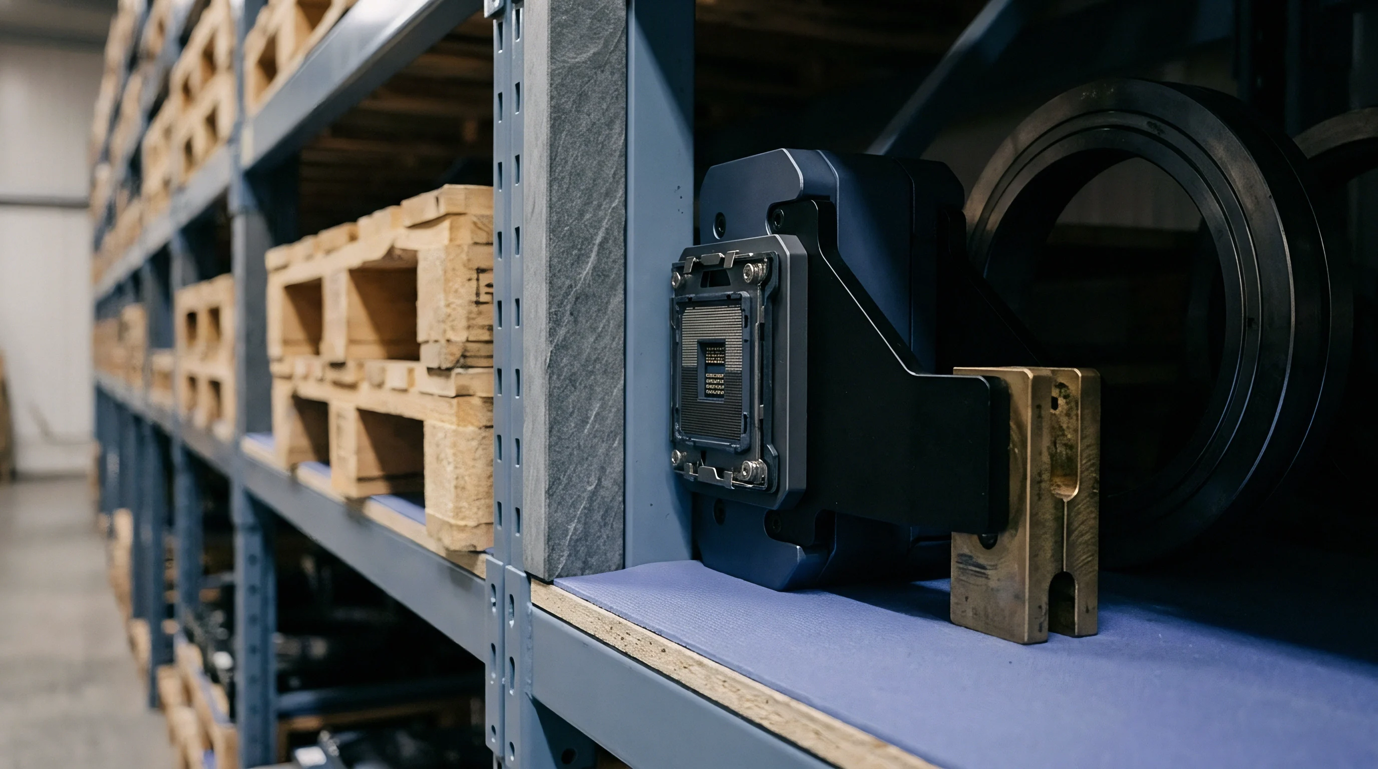
Surface Roughness Parameters at High Frequencies
Statistical topography models quantify these microscopic geometries. The Greenwood-Williamson model treats micro asperities as spherical caps with a mean radius of curvature and a Gaussian height distribution, defined by three primary parameters: summit density per unit area, mean summit radius, and standard deviation of summit heights. As force builds, these asperities deform.
At millimeter-wave frequencies where skin depth drops below 0.5 micrometers, this surface topography directly dictates high-frequency current distribution.
| Socket Contact Architecture | Typical Roughness Ra (micrometers) | Asperity Summit Density (per square millimeter) | Mean Summit Radius (micrometers) | Nominal Pin Preload Force (Newtons) |
|---|---|---|---|---|
| Precision Micro Cantilever Pin | 0.08 to 0.15 | 12,000 to 18,000 | 1.2 to 2.5 | 0.08 to 0.12 |
| Conductive Elastomeric Matrix | 0.25 to 0.50 | 4,000 to 8,000 | 3.5 to 6.0 | 0.15 to 0.25 |
| Spring-Loaded Pogo Probe Tip | 0.12 to 0.30 | 8,000 to 14,000 | 2.0 to 4.0 | 0.10 to 0.18 |
| Micro-Spring Wire Array | 0.05 to 0.10 | 15,000 to 22,000 | 0.8 to 1.8 | 0.05 to 0.10 |
Vendor specifications for test sockets routinely report averaged profile roughness rather than peak height distributions. Standard arithmetic average roughness (Ra) misses the extreme summit heights that take the initial mechanical load. Skewness and kurtosis indicate whether a surface features sharp, isolated peaks or broad plateaus; high kurtosis concentrates stress at isolated spots, accelerating localized plastic flow during early contact cycles.

Micro Contact Statistics for Precision Test Pins
Mating interfaces touch first at localized pressure points. When two metallic surfaces engage, physical contact begins at just three or four discrete summits. As load increases, these initial spots expand while secondary summits make contact, forming a cluster across the pad zone.
The spacing between individual asperities influences how high-frequency electromagnetic fields propagate across the boundary.
Even under low overall normal force, high-aspect-ratio asperities experience localized pressures that exceed the yield strength of the plating metal. Once plastically deformed, they form flattened metallic islands separated by air gaps and native oxide pockets. Above 30 GHz, these micro-voids act as capacitive gaps, creating local impedance discontinuities that reflect RF energy back into the device under test.
Initial mechanical engagement between test probe tips and device pads relies on isolated micro asperities that experience local stresses beyond metal yield limits before nominal contact force completes its stroke.
Surface contamination and native oxide layers also shape topographical behavior. Unpassivated copper or tin-lead pads carry oxide films 2 nanometers to 15 nanometers thick. Micro asperities must punch through or shear these dielectric layers to establish direct metal-to-metal paths.
While higher roughness helps rupture oxide films by concentrating force at sharp peaks, it also creates deeper valleys that collect flux residue, organic films, and wear particles. Ignoring peak height distributions during interface selection risks unpredictable contact resistance spikes and premature socket wear in production.


Deformation
Mechanical loading moves probe pin asperities through distinct deformation regimes. Touchdown begins with purely elastic strain at the summit tips. As normal force ramps up, shear stress inside individual asperities exceeds the yield threshold and plastic flow begins.
For high-frequency testing, maintaining a stable contact interface requires balancing elastic springback against plastic flattening of the tip surface.

Elastic Mechanics across Metal Surfaces
Hertzian theory describes single-asperity behavior during initial elastic compression. The contact radius of a single spherical peak against a flat surface scales with the one-third power of normal force, elastic modulus, and radius of curvature. This elastic phase stores potential energy in the crystal lattice; when load is removed, the material springs back to its original shape without permanent distortion.
Real surfaces contain millions of asperities of varying height and curvature. Greenwood and Williamson showed that under an exponential height distribution, total real contact area scales linearly with applied normal force, even though single asperities follow non-linear Hertzian mechanics. This linear scaling holds until plastic yielding dominates the zone.
Thermal expansion during temperature ramping alters asperity compression, shifting localized stresses.
Plastic deformation converts forty percent of nominal asperity peak heights into flattened plateaus when contact force exceeds 0.12 N per pin.

Plastic Flow in Plated Tip Surfaces
Plastic deformation begins when local contact pressure hits the hardness limit of the softer metal. For pure electrodeposited gold on probe tips, hardness ranges from 1.2 GPa to 2.0 GPa. Hard gold alloys with cobalt or nickel additives reach 2.5 GPa to 3.5 GPa.
Once yield starts, asperity contact area expands rapidly until local pressure drops to equal material hardness.
Repeated actuation strain-hardens the gold matrix, raising local yield strength over the first several hundred insertions and slowing further plastic flow. Severe plastic strain, however, risks micro-cracking and delaminating thin electroplated coatings. Hard nickel underlayers, used beneath gold to prevent copper diffusion, endure heavy bending stress when surface asperities undergo extreme plastic flattening.
- Mount the test socket assembly onto a precision micro-force load cell equipped with an optical displacement sensor.
- Apply incremental vertical displacement in steps of two micrometers while recording real-time contact force and micro-ohmmeter resistance measurements.
- Extract the critical force corresponding to the non-linear transition point where contact resistance stabilizes.
- Retract the probe tip and analyze the post-test surface profile using atomic force microscopy to measure permanent plastic depression depth.
During intermediate elasto-plastic loading, models by Chang, Etsion, and Evseev account for volume conservation during plastic flow, predicting metal displacement outward from flattened summit plateaus. This displaced metal forms raised rims around contact spots, altering surface topography and shifting capacitive gaps in non-contacting regions. Excessive normal force accelerates plastic creep at high temperatures, relaxing contact stress and degrading signal performance over long production runs; sockets rated for 110 GHz fail once tip deformation alters the signal launch geometry.


Constriction
Current crossing a test socket interface compresses sharply through discrete micro-asperity spots. Electric field lines converge on these tiny metal junctions, generating constriction resistance. At millimeter-wave frequencies, skin effect further restricts current flow.
The combined effect of asperity constriction geometry and electromagnetic skin depth governs total contact impedance, insertion loss, and return loss.

Which Contact Geometry Minimizes Millimeter Wave Insertion Loss?
Holm’s classical constriction model evaluates direct current through a circular contact spot of radius a. When spot radius exceeds the electron mean free path in the metal, constriction resistance scales inversely with spot radius and directly with resistivity. At room temperature, gold has an electron mean free path near 40 nanometers.
When asperity flattening creates spot radii under 100 nanometers, classical diffuse models drop in accuracy, requiring Sharvin’s ballistic transport corrections.
At radio frequencies, skin depth dictates current distribution: in gold, skin depth (δ) drops from roughly 0.50 micrometers at 24 GHz to 0.31 micrometers at 60 GHz and 0.23 micrometers at 110 GHz. Once skin depth falls below the height and width of surface asperities, high-frequency current concentrates entirely within an ultra-thin skin following the rough boundary contour.
Traversing three-dimensional micro-roughness lengthens the effective current path. Surface resistance rises above smooth-surface calculations by a factor proportional to slope and roughness amplitude, increasing resistive dissipation and pushing up insertion loss.
| Frequency (GHz) | Asperity Load State | Mean Contact Spot Radius (micrometers) | DC Constriction Resistance (milliOhms) | RF Insertion Loss S21 (dB) | RF Return Loss S11 (dB) |
|---|---|---|---|---|---|
| 28 | Elastic (Low Force) | 0.35 | 38.2 | -0.18 | -22.4 |
| 28 | Plastic (Nominal Force) | 1.20 | 11.5 | -0.08 | -28.1 |
| 60 | Elastic (Low Force) | 0.35 | 42.6 | -0.48 | -14.2 |
| 60 | Plastic (Nominal Force) | 1.20 | 12.8 | -0.19 | -21.8 |
| 77 | Elastic (Low Force) | 0.35 | 46.1 | -0.72 | -11.5 |
| 77 | Plastic (Nominal Force) | 1.20 | 14.1 | -0.27 | -18.3 |
| 110 | Elastic (Low Force) | 0.35 | 54.8 | -1.15 | -8.6 |
| 110 | Plastic (Nominal Force) | 1.20 | 16.5 | -0.41 | -15.2 |
Receiver evaluations from 24 GHz to 110 GHz under variable mechanical preload confirm that low force leaves high constriction resistance and large reflection spikes across high-frequency bands. Raising normal force flattens asperities, expands contact area, lowers constriction resistance, and smooths current paths.

Electromagnetic Scattering across Microscopic Air Voids
Gaps between non-contacting asperities act as parallel dielectric spaces filled with air or surface films. High-speed signals experience local capacitance and inductance anomalies at these micro-voids: constriction into narrow metallic channels creates parasitic inductance, while small air gaps between non-contacting plateaus form parasitic capacitance.
Below 10 GHz, parasitic capacitive reactance across asperity gaps is negligible compared to conduction through the metal. At 77 GHz and above, skin effect dominance allows gap capacitance to offer an alternate low-impedance displacement path across oxides and air spaces, driving frequency-dependent impedance shifts and reflection losses.
Compliance with high-frequency qualification standards requires maintaining total contact impedance variation below five percent across all socket test channels over hundred thousand actuation cycles.
Modeling illustrates the non-linear relationship between mechanical preload, micro-asperity deformation, and RF impedance. Consider a pogo pin contact operating at 60 GHz with gold resistivity of 2.44 × 10⁻⁸ Ω · m. Under a light force of 0.03 N, elastic contact yields 8 discrete spots averaging radius a = 0.25 μ m.
Total DC Holm constriction resistance is:
Rc = fracρ2 sum ai = frac2.44 × 10-82 × 8 × (0.25 × 10-6) ≈ 0.0061 Ω = 6.1 mΩ
Because skin depth at 60 GHz (δ = 0.31 μ m) matches asperity peak heights (0.45 μ m), path elongation increases effective RF surface resistance by a factor of 2.8. High-frequency contact impedance includes an inductive reactance Xc = 2 π f Lp from magnetic field crowding around constricted metallic necks:
Lp ≈ μ0 · a · lnleft(fracD2aright) ≈ (4π × 10-7) × (0.25 × 10-6) × ln(4) ≈ 0.435 pH
At 60 GHz, 0.435 pH of parasitic inductance per spot yields a reactive impedance of Xc ≈ 0.164 Ω. Eight parallel spots give a combined reactive contact impedance near 20.5 mΩ, dominating resistance. Increasing force to 0.12 N causes plastic yield, expanding spots to a = 1.1 μ m and reducing spot inductance to 0.18 pH; total reactive impedance drops below 4.1 mΩ, stabilizing RF return loss.
Interfacial oxide layers add non-linear tunnel resistance across constriction spots. Thin native oxides (5 nm) block DC as capacitive barriers while adding frequency-dependent RF attenuation. Standard production test specifications set tight limits on contact resistance drift and insertion loss shifts over environmental testing.


Scrub
Probe tips rely on deliberate wiping action to break surface oxides and establish low-resistance contact. Vertical socket actuation translates into horizontal movement, sliding micro asperities across target pads. This lateral movement generates shear stresses that fracture brittle oxide films and push debris clear of the contact path.

Shear Forces and Oxide Film Penetration
Native aluminum and tin oxides carry high mechanical hardness and electrical resistivity. Vertical compression alone rarely breaks these dielectric barriers without excessive, damaging normal force. Adding a transverse wiping movement induces shear failure across thin oxide films.
As wipe displacement begins, tip asperities dig into the target pad, carving microscopic metallic grooves. High shear stress ruptures surface contamination and oxide films, exposing virgin underlying metal. Fresh gold and copper atoms from both surfaces form direct metallic bonds across new contact spots under combined shear and normal force.
- Tip scrub angle must match socket housing mechanical tolerances to yield consistent lateral displacement without pin binding.
- Wipe displacement distance requires strict control between 8 micrometers and 20 micrometers to balance oxide penetration against pad cratering.
- Asperity shear modulus dictates localized tip compliance during initial transverse movement across rigid IC package pads.
- Contact force trajectory must maintain a positive slope throughout the wipe stroke to prevent mechanical tip chatter and signal dropouts.
- Debris evacuation channels cut into probe tip geometry divert solder flux and metallic flakes away from active contact zones.
Dynamic friction coefficients shift during wiping. Initial static friction reflects junction shear strength; as sliding continues, friction transitions to dynamic sliding driven by mechanical plowing and metallic adhesion. Plowing forces depend on asperity attack angles and tip radius ~ sharp asperities act like micro-cutting tools, digging deep channels into soft gold or solder pads and generating loose wear particles.

Wipe Length Optimization for Gold Interfaces
Wipe distance trade-offs balance electrical stability against contact lifespan. Excessive wipe length shears off surface asperities, stripping noble metal plating and exposing base nickel. Exposed nickel oxidizes rapidly in ambient conditions, driving contact resistance drift during thermal testing.
Specifying an eight-micrometer wipe displacement yielded a 0.35 dB reduction in insertion loss variation across fifty test sockets. Shorter wipe distances minimize metallic wear while generating enough shear stress to penetrate organic film residues. Micro-scale topography confirms that optimized wipe motion forms compact metallic plateaus without generating excessive debris.
Wipe motion clears dielectric film.
Loose metallic particles, solder flux, and dust settle into non-contacting valleys between asperities. Trapped debris prevents full pin engagement, causing sudden force drop-offs and misaligning RF impedance launches, which leads to frequent test cell stops and premature socket replacement.


Degradation
Test sockets in high-volume production undergo hundreds of thousands of insertions under thermal cycling. Continuous mechanical stress and exposure degrade micro-asperity contact zones; micro-welding, adhesive wear, fretting corrosion, and plating transfer progressively alter topography, degrading millimeter-wave signal integrity over time.
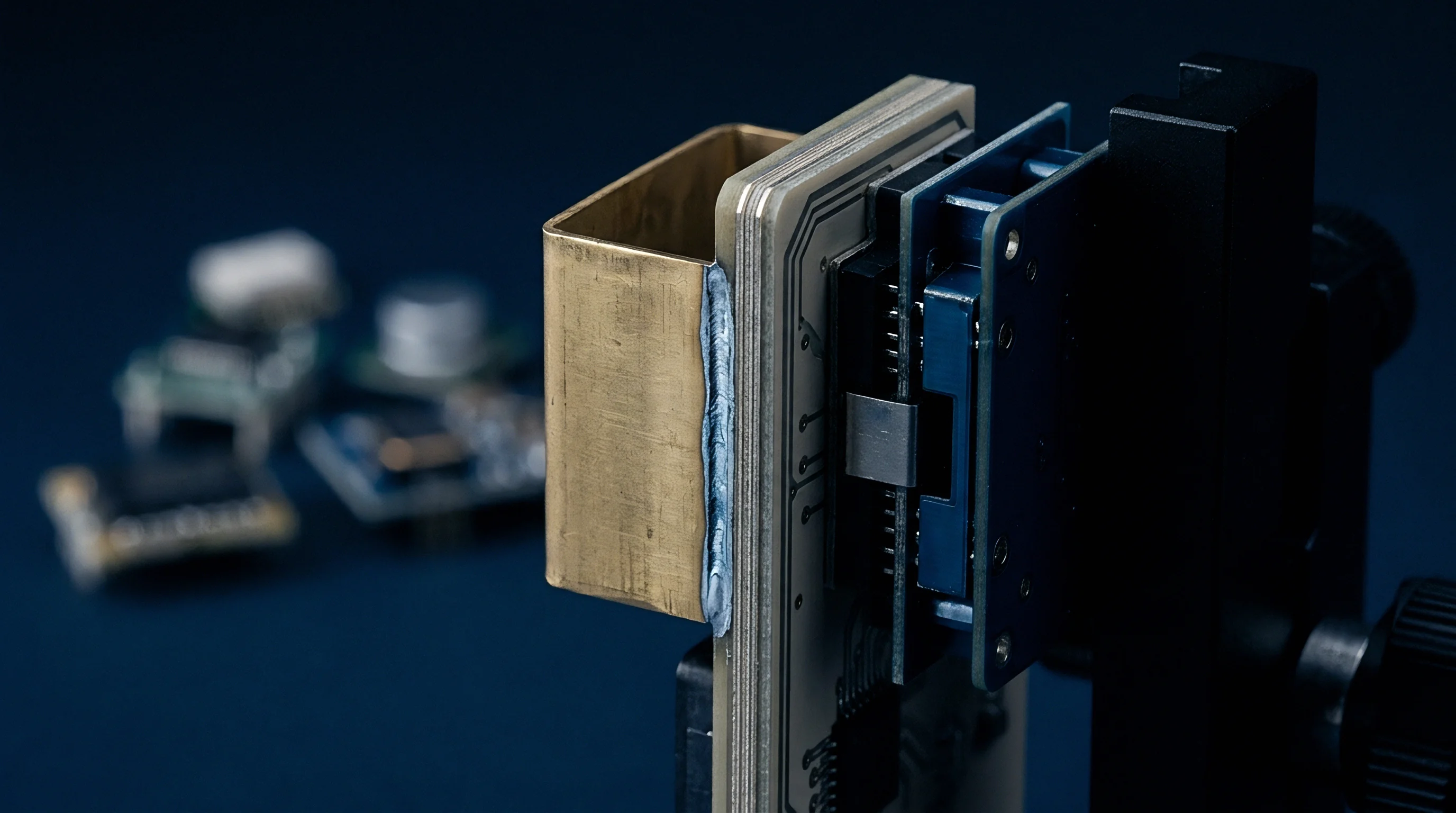
Wear Mechanisms in Automated Production Test Sockets
Adhesive wear is the primary degradation mechanism for noble metal socket interfaces. High local contact pressure fuses micro-asperity junctions; as probe tips retract, these micro-welds shear, transferring microscopic gold fragments between target pads and probe tips. This plating transfer alters tip geometry into rough, irregular projections that concentrate subsequent contact forces.
Fretting corrosion occurs when automated handler movement or thermal cycles induce micro-vibrations (1 to 5 micrometers). This relative motion repeatedly breaks and reforms contact spots, exposing fresh metal to oxygen. Oxide accumulation at asperity boundaries insulates contact spots, steadily increasing constriction resistance.
| Degradation Mechanism | Micro-Mechanical Driver | Primary RF Impact | Maintenance Trigger Threshold | Operational Intervention |
|---|---|---|---|---|
| Adhesive Plating Transfer | Micro-welding and mechanical tearing of gold asperities | S11 return loss degradation and phase ripple above 40 GHz | Insertion loss variance exceeding 0.3 dB across test channels | Precision ultrasonic solvent bath and tip replacement |
| Fretting Corrosion | Micro-vibration induced oxide layer growth | DC contact resistance spikes and transient RF dropouts | DC contact resistance exceeding 100 milliOhms | Automated abrasive cleaning pad actuation stroke |
| Plastic Tip Flattening | Excessive mechanical normal force exceeding yield strength | Impedance drop due to enlarged local capacitance | Total probe pin displacement loss of 15 micrometers | Complete test socket insert replacement |
| Particulate Contamination | Entrapment of solder flux and atmospheric debris | Resonance spikes and localized RF signal attenuation | Repeat contact failure rate exceeding 0.05 percent | Non-contact compressed air flush and chemical solvent wipe |
Excessive preload accelerates tip wear. Repeated impacts strain-harden and micro-fracture electroplated underlayers. Cracks in the nickel diffusion barrier allow copper to migrate to the surface via grain boundary diffusion during high-temperature testing (125circC), where it oxidizes into insulating film barriers across micro-asperity tips.

Maintenance Protocols for High Frequency Interconnects
Production lines use automated socket cleaning to restore micro-asperity contact. Abrasive pads mounted on dummy packages execute wiping routines to remove flux, oxide crusts, and transferred metal. While cleaning clears the tips, it also thins gold surface plating, limiting total allowable cleaning cycles over the socket’s lifespan.
Tracking contact impedance trends during automated testing catches impending interface failures before yield drops. Sockets should be replaced whenever the standard deviation of high-frequency insertion loss doubles across adjacent test channels, regardless of DC resistance readings.