Nonlinear Asperity Conduction and Passive Intermodulation Mitigation in Sub-Millimeter Radio Interfaces
Sub-millimeter interface passive intermodulation stems from non-ohmic tunneling across micro-asperity oxide gaps, mitigated by noble surface finishes and controlled flange torque.


Flange

Microscopic Contact Mechanics and Electron Tunneling
Physical contact across metallic conductor interfaces never forms a continuous planar junction; it occurs exclusively at isolated micro-asperities distributed across the mating surface, which occupy less than one percent of the apparent geometric contact area. When waveguide sections or coaxial sub-millimeter connectors couple, mechanical loading deforms these microscopic high points into discrete conduction channels known as A-spots. At operating frequencies above 100 GHz, skin depth drops below 200 nanometers, confining RF current to the micro-roughness profile of these surface asperities, where local current density spikes sharply as the skin depth falls below peak roughness heights.
Native metal oxides ~ such as cuprous oxide, aluminum oxide, and nickel oxide ~ form self-limiting insulating films between 1.5 and 5 nanometers thick over unpassivated asperities, acting as potential tunnel barriers. When mechanical pressure brings these oxidized asperities into contact, electron transport across the interface shifts from classical ohmic conduction to quantum mechanical tunneling. The current-voltage characteristic across a metal-oxide-metal micro-junction follows the nonlinear Simmons tunnel barrier model, in which electron transmission probability varies exponentially with applied RF voltage.
Under weak excitation, the junction shows quasi-linear contact resistance, but as RF power increases, the electric field gradient inside the ultra-thin oxide layer exceeds 106 V/cm, driving non-ohmic conduction that distorts the propagating wave.
A surface roughness average exceeding 80 nanometers RMS at a 140 GHz interface elevates passive intermodulation power by 14 dB under a 20 dBm tone power input.
Constriction resistance dominates the overall interface impedance. Current lines bend sharply to squeeze through narrow A-spot contact regions, pushing local current density beyond 107 A/cm2. This severe constriction works alongside non-ohmic tunnel conduction through residual oxides to form a distributed matrix of nonlinear impedances across the interface plane.
At sub-millimeter wavelengths, where interface tolerances approach a fraction of the wavelength, minor variations in surface topography or clamping pressure reconfigure the spatial layout and nonlinear behavior of these micro-junctions.
Whether quantum transport across sub-nanometer monolayer oxide voids dominates intermodulation generation over thermal modulation of asperity bulk conductivity at high ambient temperatures remains unsettled.


Mixing

Intermodulation Distortion in Sub-Millimeter Channels
High-frequency carriers passing across nonlinear junctions generate unwanted spectral components in co-located channel assignments. When two high-power transmit tones at frequencies f1 and f2 cross an interface with nonlinear asperity contacts, the non-ohmic current response acts as a spatial frequency mixer, spawning odd-order intermodulation products ~ predominantly third-order (2f1 – f2 and 2f2 – f1) and fifth-order (3f1 – 2f2 and 3f2 – 3f1) signals that can blind receiver channels.
Sub-millimeter wireless architectures ~ including wideband point-to-point links in D-band (110 GHz to 170 GHz) and G-band (140 GHz to 220 GHz) ~ rely on wide channel bandwidths and tight duplex spacing. Third-order passive intermodulation products generated at waveguide flanges or horn antenna mounts routinely fall inside the passband of adjacent high-sensitivity receiver front-ends. Because sub-millimeter low-noise amplifiers run with noise figures around 4 to 7 dB, even weak intermodulation signals rising above -120 dBm degrade sensitivity, set packet error rate floors, and shorten maximum link distance.
| Interface Standard | Frequency Band (GHz) | Transmit Power (dBm) | RMS Roughness (nm) | 3rd-Order PIM Level (dBm) | Desensitization Risk |
|---|---|---|---|---|---|
| WR-8.0 (UG-387/U) | 90 – 140 | +23 | 120 | -98 | Severe receiver throughput drop |
| WR-6.5 (IEEE 1785.2) | 110 – 170 | +20 | 60 | -112 | Moderate link margin loss |
| WR-5.1 (Precision) | 140 – 220 | +18 | 35 | -124 | Acceptable baseline floor |
| WR-3.4 (Precision) | 220 – 330 | +15 | 15 | -132 | Negligible interference limit |
Generated intermodulation scales nonlinearly with transmit power: third-order intermodulation power increases by 3 dB for every 1 dB rise in input carrier power. At sub-millimeter frequencies, where power amplifiers operate near saturation to counter atmospheric path loss, slight increases in output power produce disproportionate intermodulation growth across raw interface asperities. Local thermal modulation of contact spots under pulsed or modulated RF envelopes further spreads this noise across adjacent sub-carriers in orthogonal frequency-division multiplexing systems.
Smoothing surface roughness profiles below the local skin depth suppresses odd-order mixing products more effectively than increasing mechanical clamping torque.


Finish

Metallurgical Coatings and Passivation Coatings
Metallurgy at high-frequency wave interfaces determines long-term oxide growth and non-ohmic conduction. Unpassivated copper and aluminum alloys form dense native oxides within hours of exposure to air. Depositing noble metal barrier stacks across interface surfaces prevents oxide growth while maintaining high conductivity across micro-asperity contact spots, avoiding the millimeter-wave attenuation typical of ferromagnetic barriers.
Electroless nickel immersion gold is a standard finish for printed circuit board edge launches and micro-coaxial connectors, but the underlying nickel diffusion barrier is strongly ferromagnetic. At sub-millimeter wavelengths, ferromagnetic nickel layers introduce severe hysteresis losses, reduce RF power handling, and create magnetic non-linearities that amplify passive intermodulation. Specifying non-magnetic barrier layers ~ such as high-phosphorus electroless nickel-phosphorus (above 10 percent by weight) or direct palladium stacks ~ suppresses these magnetic distortion products.
Self-assembled monolayers of organic thiols offer an ultra-thin alternative for waveguide flange passivation. An organic monolayer forms a packed dielectric shield less than 2 nanometers thick directly over gold or silver surfaces, sealing micro-asperity voids against oxygen and moisture ingress without adding a thick barrier that would impede low-resistance tunneling. Alternatively, gold-cobalt hard gold over non-magnetic copper-phosphorus passivates the interface against fretting corrosion while keeping contact non-linearity low over repeated mating cycles.
A contract clause mandating non-magnetic palladium barrier plating eliminates ferromagnetic intermodulation products that otherwise void sub-THz link margin warranties.
Electroless silver plating delivers low initial insertion loss and quiet intermodulation floors owing to silver’s high conductivity and low oxide barrier height. However, silver tarnishes when exposed to trace sulfur gases, forming semiconducting silver sulfide films. A silver sulfide micro-junction acts as a Schottky diode across contact asperities, driving up intermodulation after brief field exposure.
Electroplated gold over a dense palladium-nickel diffusion barrier provides far more stable performance over multi-year deployments in humid environments.
Selecting standard nickel-underplate formulations on millimeter-wave flanges imposes an immediate 10 dB link budget penalty and risks thermal runaway under high-power illumination.


Clamp

Deformation Mechanics and Pressure Relaxation
Compressive mechanical load flattens microscopic surface peaks during initial fastener engagement, pushing micro-asperities past their yield strength. Plastic deformation ruptures brittle native oxide films and forces direct metal-to-metal contact across opposing surfaces, establishing low-resistance A-spots. High initial clamping pressure maximizes this metallic contact area and lowers the interface’s overall nonlinear response.

How Does Torque Relaxation Induce Passive Intermodulation Drift?
Sustained mechanical stress triggers room-temperature viscoelastic creep in aluminum and copper flange bodies, causing fastener torque to decay over time. As clamping pressure degrades, elastic spring-back unloads compressed micro-asperities. The physical contact area of individual A-spots shrinks, separating bare metal surfaces and re-establishing nanometer-scale gaps across residual oxide fragments.
These reopened micro-gaps act as quantum tunneling barriers and metal-semiconductor junctions, driving measured passive intermodulation levels up by 15 to 25 dB over months of field operation.
- Asperity Unloading Drift Contact pressure loss permits elastic spring-back of flattened micro-peaks, re-introducing oxide tunnel gaps across the contact plane.
- Differential Thermal Shear Dissimilar expansion coefficients between fasteners and flange bodies shear contact micro-welds, creating micro-gaps.
- Oxide Re-ingress Ambient humidity penetrates microscopic gaps around unloaded contact zones, growing non-ohmic semiconductor film layers.
- Vibrational Fretting Corrosion Micro-motion from mechanical vibration grinds surface asperities, creating localized conductive debris and fluctuating junction impedances.
Thermal cycling accelerates mechanical contact degradation. Sub-millimeter radio front-ends experience ambient temperature swings combined with internal self-heating from power amplifiers. Differential thermal expansion between stainless steel screws and brass or aluminum flanges generates cyclic shear stress across the mating plane.
This stress breaks local micro-welds formed during initial torque-down, creating micro-abrasion debris that oxidizes rapidly. Interfacial movement as small as 50 nanometers causes rapid instability in passive intermodulation performance.
| Fastener Spec | Initial Torque (N·cm) | Clamping Pressure (MPa) | Post-100 Cycles PIM Rise (dB) | Contact Resistance Drift (mΩ) |
|---|---|---|---|---|
| 4-40 Stainless (Standard) | 55 | 12.5 | +18.2 | +4.1 |
| 4-40 Stainless w/ Belleville | 55 | 12.1 | +2.4 | +0.3 |
| Precision Alignment Pin (UG-387) | 40 | 8.8 | +14.6 | +3.2 |
| IEEE 1785 Precision Alignment | 40 | 15.4 | +1.1 | +0.1 |
Thermal cycling always degrades un-passivated micro-contacts faster than constant elevated mechanical loading.
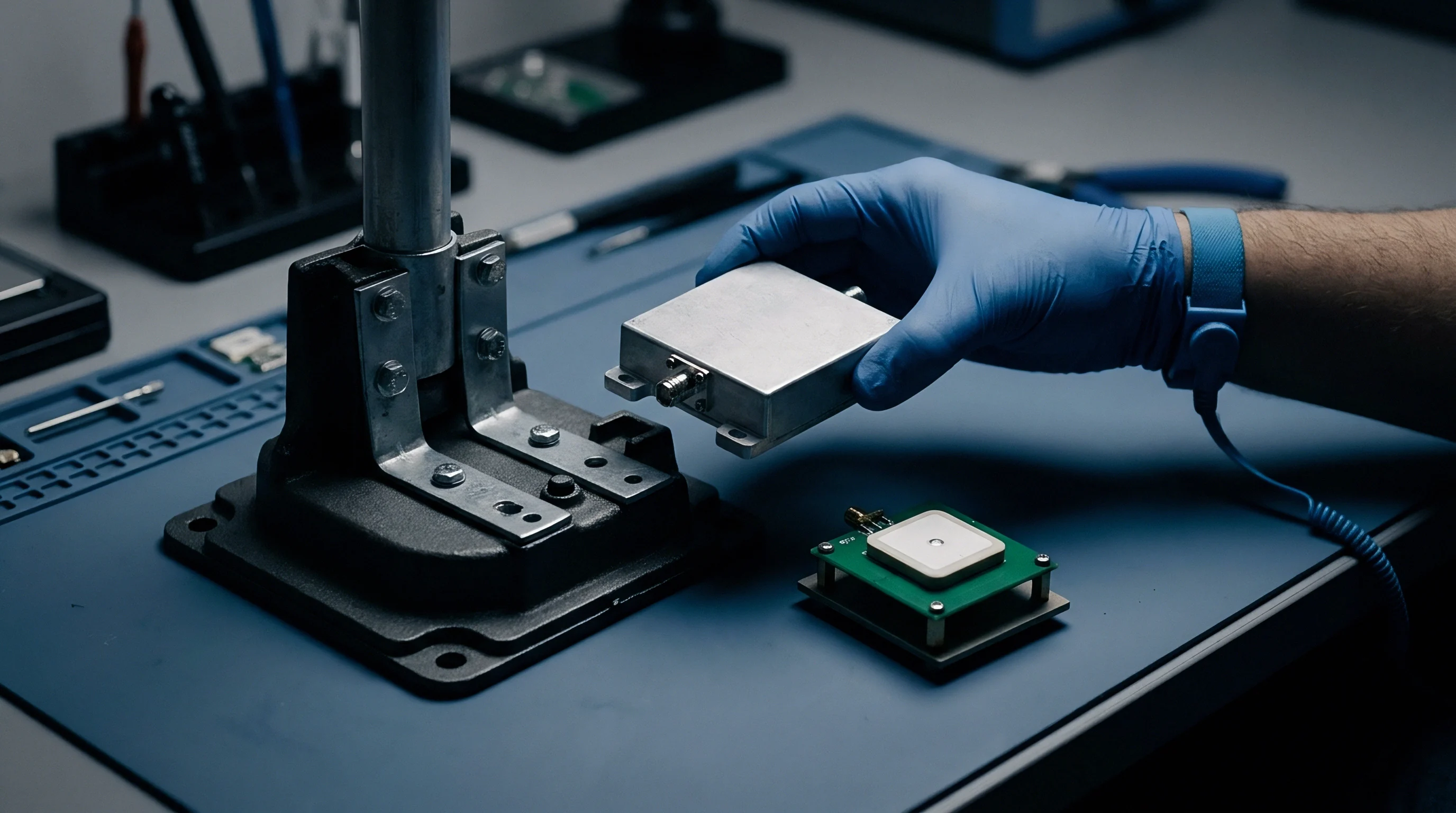
Proper fastener hardware mitigates long-term pressure relaxation. Integrating Belleville spring washers into waveguide flange fastener stacks maintains constant compressive force through thermal expansion and creep cycles. The washers absorb dimensional changes in the flange assembly without letting clamping pressure drop below the plastic deformation threshold of the asperities, keeping the intermodulation floor at its initial baseline.
Module vendors frequently attribute shifting receiver noise floors to field torque variances rather than addressing underlying mechanical stress relaxation in un-doweled flange assemblies.

Sweep

High-Dynamic-Range Verification Methodologies
Bench measurement of residual intermodulation floors requires high-isolation signal routing and extremely low internal system distortion. Characterizing passive intermodulation above 100 GHz demands custom test benches. Dual-tone test signals from phase-locked synthesizers feed separate high-power solid-state amplifiers, with directional couplers isolating the tones.
Signal combiners must deliver over 40 dB of inter-port isolation to keep high-power tones from mixing within the output stages of the opposing source amplifiers.
- Source Isolation Calibration Verification of dual-tone combiner isolation ensures carrier cross-bleeding does not generate bench-level intermodulation prior to the test interface.
- Residual Floor Baseline Direct back-to-back calibration of high-rejection waveguide filters establishes the instrumentation noise limit.
- Thermal Equilibrium Soaking Thermal stabilization of the device under test under full transmit power eliminates transient expansion noise during frequency sweeps.
- Dual-Tone Frequency Stepping Automated stepping of tone separation across the full operating band detects narrow-band resonance modes in asperity conduction.
Narrow-band high-rejection cavity filters separate low-level intermodulation products from high-power fundamental transmit signals before passing the sample to a spectrum analyzer or vector receiver. The residual intermodulation floor of the bench must sit at least 10 dB below the specification limit for the device under test. High-dynamic-range load-pull measurements sweep both tone spacing and absolute power levels to extract the nonlinear expansion coefficients of the interface.
Sweeping tone power levels allows engineers to separate third-order tunneling intermodulation from thermal envelope intermodulation. Pure tunneling junctions exhibit a strict 3:1 decibel slope between third-order product growth and fundamental power increases. Thermal intermodulation, driven by periodic heating of contact asperities, shows a slope of 5:1 or higher at narrow tone spacings.
Pinpointing the dominant mixing mechanism helps target remediation, separating surface finish flaws from mounting deficiencies.
Incorporating standard MIL-DTL-3922 sweep qualification thresholds directly into interface supply agreements transfers liability for field-level receiver desensitization back to the waveguide component manufacturer.

Procurement

Interface Specification and Link Budget Safeguards
Sourcing sub-millimeter radio front-end modules requires balancing machining tolerances against system performance limits. Engineering drawings for sub-millimeter waveguide interfaces must specify tight surface texture controls. Diamond-turned flange manufacturing achieves surface roughness averages below 15 nanometers RMS, eliminating height spikes that act as high-field tunnel junctions, though precision machining increases unit cost while unmitigated carrier power drives intermodulation exponentially.
Sub-millimeter link budgets leave little room for unexpected interface losses. At 145 GHz, atmospheric oxygen absorption and rain attenuation consume up to 15 dB/km of margin. If passive intermodulation lifts the receiver noise floor by 6 dB, the effective range of a high-capacity backhaul transceiver drops by more than 35 percent.
Procurement standards must enforce strict verification metrics on all incoming interface hardware to protect link distance.
| Interface Class | RMS Roughness Spec (nm) | Plating Specification | Unit Cost Premium (%) | 5-Year Degradation Risk |
|---|---|---|---|---|
| Commercial Standard | > 120 | Flash Gold over Standard Nickel | Baseline | High (15-25 dB noise floor rise) |
| Precision Telecom | 35 – 60 | ENEPIG (High-Phosphorus Ni) | +45 | Low (< 3 dB noise floor rise) |
| Sub-THz Military/Aerospace | < 15 | Direct Gold over Palladium Stack | +130 | Negligible (< 1 dB drift) |
- Surface Finish Certification Requirement for optical profilometry inspection data confirming micro-roughness bounds across every production lot.
- Plating Barrier Verification Mandatory X-ray fluorescence layer thickness reports confirming non-magnetic nickel-free barrier stack integrity.
- Torque Retention Guarantee Insertion of Belleville washer spring stacks in flange fastener calls to maintain minimum interface clamping stress.
Sub-millimeter wave intermodulation power grows at three times the decibel rate of carrier power expansion.
Purchasing contracts should explicitly bind module suppliers to maximum acceptable passive intermodulation floors, measured under dual-tone stress tests prior to lot acceptance. Specifying micro-geometry tolerances along with non-magnetic metallurgical barrier stacks prevents early field failures. Protecting the radio interface at the micro-asperity level ensures sub-millimeter wireless networks maintain design throughput and spectral efficiency over their operational deployment lifecycles.
The true landed cost of a sub-millimeter radio interface includes not just the purchase price on the invoice, but also the long-term margin reserves set aside to absorb unmitigated intermodulation over five years in the field.