Meaning
Electronic oscillator configurations provide stable clock signals for microcontrollers using a single active inverter, a crystal, and two external capacitors. The pierce oscillator is widely used in smart devices because of its low power consumption, high frequency stability, and ease of integration into digital integrated circuits. Circuit designers connect the crystal across the feedback loop of the inverter to establish the required phase shift for oscillation.
The active circuit relies on the external load capacitors to define the precise frequency of operation.
Crystal Integration
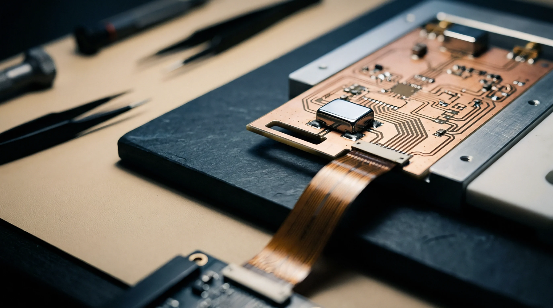
Board layout around the feedback loop determines the susceptibility of the clock circuit to electromagnetic interference. High-impedance traces on the printed circuit board act as antennas, which can couple digital noise into the oscillator input. Positioning the crystal and the load capacitors close to the microcontroller pins minimizes this trace loop area.
Integrating a series resistor in the output path protects the crystal from overdrive and reduces harmonic emissions.
Startup Margin
Impedance mismatch or high board leakage current can prevent the circuit from starting up reliably. The gain margin must exceed five times the circuit loss across the entire operating temperature range to guarantee reliable startup.
Power Consumption
Optimizing the feedback loop currents allows the system to run on minimal energy during sleep cycles. Low-power designs use small crystals with low motional resistance to minimize the active current drain of the clock.