Meaning
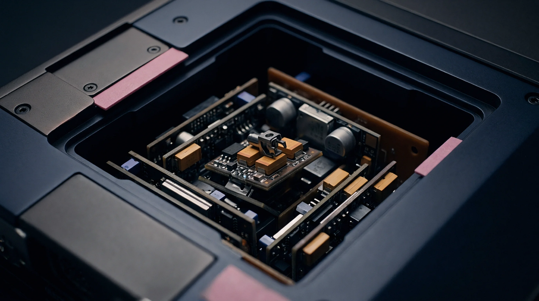
Rigorous verification of the physical interface between an automated assembly system and a device under test establishes the dimensional and electrical accuracy required for high volume production environments. A test jig calibration aligns the mechanical alignment pins, probe contact forces, and signal routing impedance of the fixture against a primary reference artifact to ensure consistent output quality. This procedure defines the operating boundaries of the test environment by mapping fixture degradation, such as contact tip wear or spring fatigue, to a known baseline performance.
It establishes a repeatable link between raw electrical signal acquisition at the contact point and the final measured data stored in a production database. The process remains applicable to any fixture architecture where physical contact or proximity affects the reliability of electrical measurement or mechanical registration.
Mechanical Alignment
Proper geometry of the assembly ensures that force distribution remains uniform across all contact points during the mating cycle. The test jig calibration quantifies the deviation of probe tips from target pads on a circuit board by measuring positional offset with an optical coordinate system. High accuracy in this stage prevents mechanical damage to delicate surface mount components while maintaining stable signal transmission for automated testing systems.
Operators check the vertical travel of each spring probe to verify that consistent pressure occurs without exceeding the yield strength of the test pads or the jig structure itself. Stable mating allows for reliable resistance measurements during the final quality audit of a communication module.
Signal Integrity
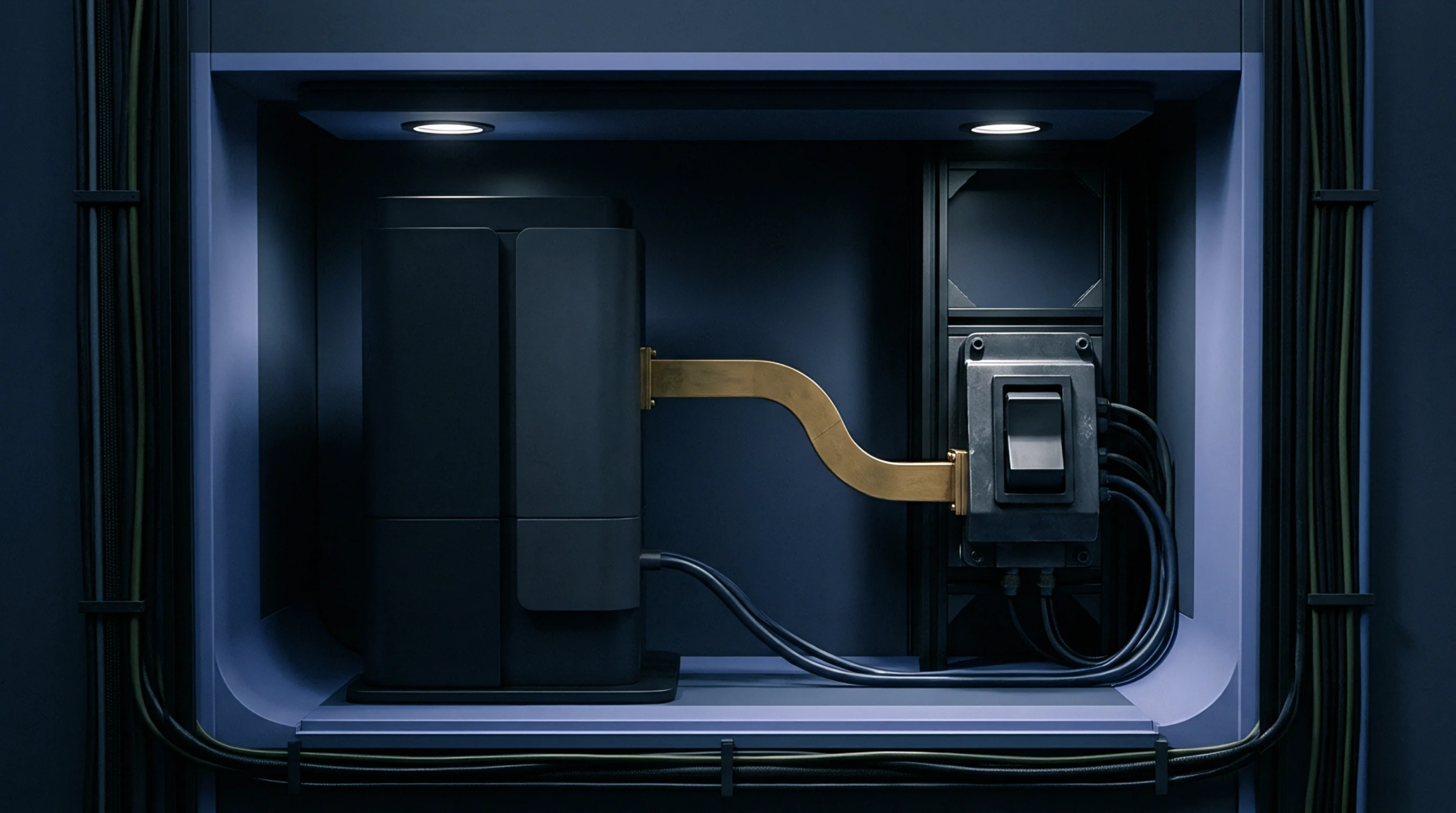
Impedance variations within the test interface introduce noise or parasitic effects that distort high frequency radio signals measured during production line validation. The test jig calibration confirms that the electrical path length and shielded connectivity match the specified transmission requirements for the device under test. Technicians perform network analysis to map signal loss across the cabling and connector blocks attached to the fixture.
This data correction accounts for the specific insertion loss of the jig, allowing the system software to subtract fixture noise from the actual device performance. Ensuring signal fidelity prevents false failures during the inspection of complex smart devices that operate within narrow radio frequency bands.
Certification Interval
Determining the recurrence of verification cycles requires evaluation of environmental factors like vibration, ambient humidity, and total usage cycles per shift. Frequent operation cycles accelerate mechanical wear and shift the calibration baseline, which necessitates short maintenance windows for fixtures subjected to high throughput manufacturing. Establishing a defined interval ensures that measurement uncertainty stays within the tolerances specified by the internal quality system for mass production.
Records from each verification event serve as proof that the test system maintained accuracy throughout a production run of communication assemblies. Regular adjustment of these test fixtures maintains consistent product performance across varying manufacturing sites.