Dynamic Thermal Hysteresis and Structural Stress Relaxation in Relocated Optical Scale Metrology Frames
Relocated metrology frames require torque release, thermal soak, and interferometric mapping to eliminate structural stress relaxation and dynamic thermal drift.


Transit
A precision metrology frame carrying a long-baseline optical scale faces both shock loading and uncontrolled temperature swings during transit. Road vibration and handling jar the rail supports, while unconditioned freight holds or staging docks subject the assembly to sub-zero lows and high ambient heat. Scale substrates made from low-expansion materials like Zerodur, Invar 36, or fused silica have thermal expansion coefficients that diverge sharply from their steel, cast iron, or aluminum support beds.
Transit vibration overcomes the friction that maintains the calibrated relationship between these mismatched materials.
When ambient shifts hit a frame already vibrating under road or air transit, the constraint interfaces slip and stick continuously. The scale cannot settle back to its geometric baseline once temperatures normalize, leaving an unrepeatable distortion along the primary measurement axis. Machine tool builders and semiconductor inspection integrators routinely measure positioning errors of 2 to 15 micrometers across a two-meter travel envelope right after a machine moves.

Transport Shock Spectra and Rail Displacement
Crated equipment regularly encounters 3 g to 10 g shock transients along vertical and lateral axes during air and overland freight. These acceleration peaks generate local bending moments along linear encoder backbones mounted to long beds. Clamping mechanisms designed to accommodate differential thermal expansion in a controlled room either yield plastically or slip outright when hit with high transient inertia.
Many scale assemblies use kinematic or semi-kinematic spring clamps to isolate the scale from bed expansion. In transit, dynamic spikes overcome the clamp springs, letting the scale shift within its track. The resulting micro-strains remain after the load drops away, locking tensile or compressive stresses across the scale length.
Kinematic mounts subjected to transport vibration above 2.5 g peak acceleration exhibit an unrecoverable position offset averaging 1.8 micrometers across a two-meter baseline.

Dynamic Hysteresis across Uncontrolled Thermal Enclosures
Temperature swings in transit drive structural frames through asymmetric expansion and contraction. When container temperatures drop, thin outer members cool well ahead of heavy internal ribs, setting up transient bending couples through the casting or weldment.
Friction at the mounting points keeps the frame from contracting along the same path it took while expanding. This creates a mechanical hysteresis loop between heating and cooling legs. Even after returning to a nominal 20 degrees Celsius cleanroom setting, the frame holds residual geometric warp.
Its baseline has shifted, requiring extended thermal soaking and stress relief before any calibration attempt is valid.
- Interfacial adhesive shear strain develops when organic bonding layers between scale segments and the substrate drop to sub-zero temperatures during transit.
- Preload loss in spring-element mountings accumulates under sustained low-frequency road vibration over long freight routes.
- Kinematic contact point fretting produces microscopic wear debris that relocates the virtual pivot center of the scale assembly.
- Transient bow induced by temperature gradients locks stress into rigid clamps if a cold frame is unpacked too quickly into a warm cleanroom.
Whether transient vibration damping during transit actually prevents long-term frame creep, or merely delays its release until cleanroom thermal cycling starts, remains an open operational question.

Joint
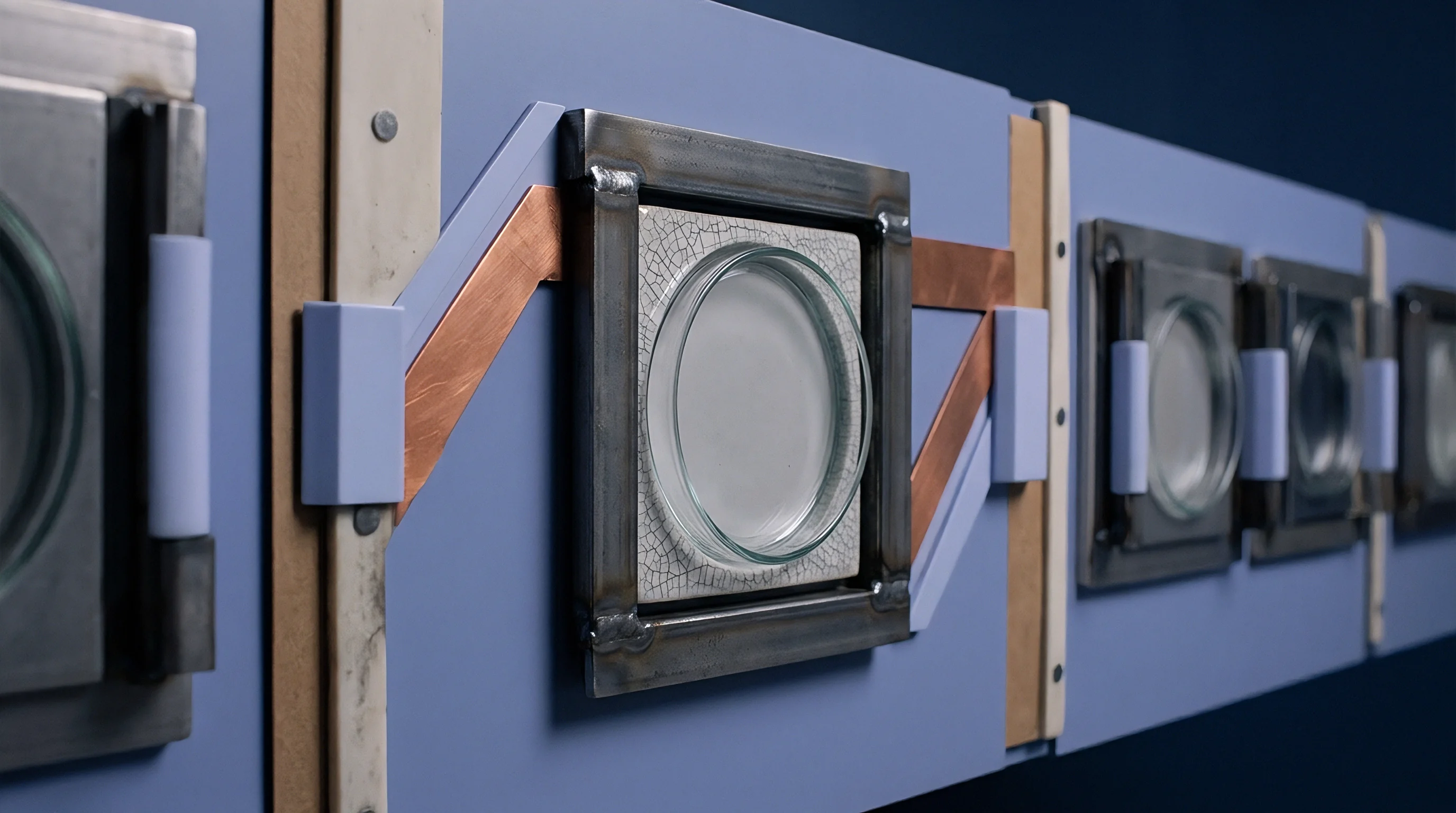
Bolted joints are the main source of unrecoverable hysteresis in relocated metrology frames. Interfaces joining granite beds, cast iron bases, and adapter plates rely purely on friction for alignment, and shipping shocks routinely exceed the friction threshold across those mating faces, producing localized micro-slip.
As ambient temperatures shift, differential thermal expansion between dissimilar parts generates shear across the bolt pattern. When temperatures return to normal, interface friction keeps the joint from settling back to its original position, locking the assembly into a pre-strained state. Over subsequent months of operation, this trapped strain slowly bleeds out, showing up as drift in encoder feedback.

Does Thermal Cycling Fully Recover Mechanical Alignment?
Thermal cycling in a bring-up bay is standard practice, but temperature changes alone cannot reset friction-locked joints. Micro-slip under thermal stress is directional, governed by localized roughness, torque scatter, and oxide films. The joint shifts along the path of least resistance as it expands, but surface asperities interlock on the return stroke, preventing full mechanical recovery.
Thermal cycling without mechanical release merely drives the structure into an alternate metastabilized condition instead of restoring its original geometry. The encoder reads the resulting warp as a non-linear calibration error. True baseline recovery requires mechanical stress relief or controlled bolt torque cycling on the cleanroom floor.
| Material Pair | CTE Differential (ppm/K) | Micro-Slip Threshold Strain | Hysteretic Position Offset (µm/m) |
|---|---|---|---|
| Invar 36 / Cast Iron HT250 | 9.8 | 45 microstrain | 1.2 to 3.4 |
| Zerodur / Granite (Black) | 6.2 | 30 microstrain | 0.8 to 2.1 |
| Fused Silica / Aluminum 6061-T6 | 22.5 | 85 microstrain | 4.5 to 11.2 |
| Invar 36 / Structural Steel S355 | 10.3 | 50 microstrain | 1.5 to 4.0 |

Micro-Slip Mechanics at Fastener Interfaces
Fastener preloads drop under combined shipping shock and thermal shear. Expansion mismatches between steel bolts and the clamped structure change the effective clamping force as temperatures climb, while heat lowers material yield points and accelerates micro-creep across the mating faces.
Variations in bolt tension leave contact pressure uneven across the joint. Heavy-pressure contact zones behave as fixed pivot points while lighter regions slip around them, warping the frame and twisting the scale guide rail into pitch, yaw, and roll errors.
Thermal equilibration of a relocated metrology frame completes only when the spatial gradient across all structural ribs falls below the sensor ambient noise floor.
Leaving shear-loaded interface bolts untouched after transit traps mechanical strain inside the frame indefinitely.

Strain
Long-term calibration drift after a move is dominated by internal stress relaxation within the frame itself. Cast iron, welded steel, and synthetic granite beds all carry residual stresses from casting, welding, machining, and heat treating, which factories stabilize prior to delivery using thermal cycling or vibratory aging.
Rigging, crane picks, transit vibration, and temperature excursions upset this equilibrium, injecting strain energy back into the metal lattice or epoxy binder. Structural relaxation then proceeds logarithmically over time: transit energy triggers dislocation movement in cast structures and micro-cracking in mineral castings, kicking off a secondary settling phase that can persist for months.

Residual Stress Activation via Transport Vibration
Freight vibration provides the activation energy for residual stress release. Sustained low-frequency shaking superimposes cyclic loads onto locked-in manufacturing stresses, and wherever the combined load exceeds local micro-yield limits, plastic deformation occurs.
This localized yield distorts frame geometry at sub-micrometer scales. For metrology tools working to nanometer-per-meter tolerances, subtle lattice shifts degrade scale calibration, twisting the backbone along its length and throwing the readhead out of alignment.

Time-Dependent Structural Relaxation Curves
Take a 3-meter cast iron metrology bed shipped across climate zones, encountering a 40 Kelvin temperature swing in freight. If internal residual stresses in the structural ribs average 15 Megapascals and transit imparts cyclic loads of 3.5 g at 12 Hertz over a 48-hour trip, the frame arrives in an energized state before reaching a cleanroom stabilized to 20.0 degrees Celsius within 0.05 Kelvin.
Tracking scale reference marks through a 168-hour soak reveals an exponential relaxation profile. In the initial 24 hours, dislocation motion produces drift at 0.35 micrometers per meter per day. Between hour 24 and hour 72, drift drops to 0.08 micrometers per meter per day, eventually leveling off near an asymptotic floor of 0.01 micrometers per meter per day by hour 168, leaving a total positional offset of 2.1 micrometers across the scale axis.
Calibrating the machine at hour 12 invalidates the correction matrix almost immediately, as continued relaxation shifts the baseline another 1.2 micrometers over the following six days while the casting settles toward equilibrium.
ISO 10360-2 acceptance compliance demands ambient thermal gradient limits written directly into the rigging bill of lading.
Overlooking internal stress relaxation leads directly to failed acceptance audits, unexplained measurement drift in production, and uncompensated volumetric errors across the machine volume.


Artifact
Re-establishing scale accuracy after transport requires physical reference standards to separate bed warp from encoder graduation errors. Laser interferometers and calibrated two-dimensional grid plates map the mechanical state of the moved frame before engineers push correction tables to the controller.
Soak protocols must precede any artifact verification. The frame rests in an enclosure held to strict temperature, humidity, and airflow limits, with surface-mounted sensors tracking internal thermal gradients until the structure achieves equilibrium across all three axes.

Laser Interferometric Mapping of Frame Distortion
Interferometric runs measure straightness, pitch, yaw, and linear positioning error along the encoder track. Because the beam serves as a fixed length reference, multi-axis optics can measure six degrees of freedom simultaneously, decoupling mechanical rail sag from thermal expansion.
These scans highlight non-linear pitch and roll caused by slipped joints or relaxing castings. Because small angular tilts produce significant Abbe errors at the scale reading plane, the controller’s volumetric compensation map must integrate the full multi-axis profile to restore machine accuracy.

Stabilization Protocols for Relocated Scale Frames
The stabilization protocol relieves mechanical pre-strain and confirms thermal equilibrium before final optical calibration begins.
- Position the frame on vibration isolation mounts inside the climate-controlled cleanroom.
- Attach resistance temperature detectors at six structural datums along the scale backbone.
- Log ambient and iron temperatures until structural gradients fall below 0.05 Kelvin per hour.
- Set up laser interferometer optics along the primary measurement axis using low-expansion invar fixtures.
- Run a twenty-one point bi-directional measurement cycle over the full travel length to map hysteresis.
- Introduce controlled steps of plus and minus two Kelvin while logging offsets at every scale marker.
- Calculate the residual thermal expansion coefficient and friction hysteresis matrix for upload into firmware.
Bolted structural joints store mechanical strain during transit that converts into slow dimensional drift over months of static room operation.
A frame that checks out within factory optical tolerances immediately after uncrating still requires a full thermal soak before calibration.


Recourse
Contracts covering machine moves, tool transfers, and turnkey installations require unambiguous technical risk boundaries. When relocated equipment fails initial accuracy acceptance, disputes over fault inevitably follow unless sourcing terms cleanly divide carrier handling limits from re-commissioning engineering scope.
Buyers, integrators, and riggers work under incompatible incentives. Freight haulers cap liability strictly at shock logger thresholds, while precision integrators refuse to guarantee tool performance until the bed reaches verified thermal and mechanical stability. Without defined handoff criteria, disputes over who funds extended stabilization and laser compensation hours can stall tool sign-off.

Scope Boundaries between Logistics and Precision Bring-Up
Relocation contracts should define explicit handoff conditions between the transport hauler and the bring-up engineers. Carriers are obligated to deliver crated equipment to climate-controlled staging without exceeding axis-specific acceleration limits, and engineering assumes custody only after reading shock logger files and verifying the hardware against transit criteria.
If sensor downloads show shock events above contractual ceilings, inspection costs and joint torque verification default to the carrier. If transit loads stay within envelope but hysteresis still corrupts accuracy, bring-up expenses shift to the buyer or OEM under agreed non-recurring engineering rates.

Commercial Terms for Relocation Calibration Guarantees
OEM warranties for moved metrology frames hinge on verified environmental histories throughout shipping and staging. Coverage is voided if the frame sits in unconditioned storage or suffers thermal shock from premature unpacking. Procurement terms must detail mandatory soak intervals, bolt re-torquing protocols, and artifact runs required ahead of final sign-off.
Purchasing teams protect capital expenditure by tying milestone payments directly to stability metrics, holding back final retainage until the reassembled system passes a continuous 168-hour drift test in the cleanroom. That milestone ties commercial release to verified machine capability rather than offloading from a truck.
- Environmental shock logging records accompany the handover packet prior to cleanroom entry.
- Thermal hysteresis mapping data establishes the pre-move baseline before crate loading.
- Joint retorque authorization forms define exact torque patterns and clamp preloads for field crews.
- Interferometric zero-point verification confirms whether transit loads caused permanent micro-yield.
Writing ASME B89.4.19 section 5 settlement provisions into shipping agreements assigns post-move recalibration and alignment costs directly to the hauler whenever transit sensors record shock events beyond the agreed threshold.