Dynamic Transient Noise Margins across Sub-Five Nanometer Interconnect Upgrades
Backside power grids preserve sub-5nm transient margins by cutting rail resistance, but signoff demands vector-based AC simulation to prevent silent field drops.


Droop
Nominal supply sits at 700 millivolts. When digital logic blocks switch states within sub-picosecond intervals, instantaneous current demands pull the internal rail down toward logic threshold boundaries. Static analysis measures steady-state resistive drops across power grids well enough, but advanced nodes break ohmic approximations during functional clock bursts.
Inductive parasitics in on-chip distribution wiring and package micro-bumps combine with steep current slew rates exceeding ten amperes per nanosecond. The resulting voltage drop lowers drive current across fin-shaped and nanosheet field-effect transistors, slowing signal propagation and causing timing violations along synchronous paths.
At sub-five nanometer geometries, metal pitches shrink below twenty-two nanometers. Narrower tracks squeeze conductive cross sections, driving up parasitic resistance per micron while crowding adjacent signal lines into tight capacitive proximity. Transient noise margin is the maximum instantaneous voltage perturbation a logic gate can take before outputting an incorrect state or shifting a clock edge beyond recovery.
As operating rails are lowered to control thermal dissipation, that noise threshold drops below fifty millivolts, making high-density registers far more vulnerable to bit errors.
Transient supply fluctuations erode gate overdrive voltages, extending cell propagation delays beyond budgeted clock cycles.

High Frequency Voltage Collapse at Advanced Nodes
Inductive rail bounce stems directly from clock-tree activation. Simultaneous switching across dense execution pipelines draws sharp current spikes from local distribution rails. Package interconnects carry lumped inductances between twenty and one hundred picohenries, generating a local L di/dt voltage dip before charge reservoirs can replenish through power bumps.
Lower metal layers M0 through M3 add distributed resistance that prevents neighboring decoupling sites from supplying current quickly enough, causing local voltage to drop sharply and hurting transconductance in nearby standard cells.
Modern logic blocks rely on power-gating switches to curb standby leakage. Turning sleep transistors back on pulls heavy inrush current into the local grid. Without carefully staggered gate timing, local supply rails can drop by more than fifteen percent of nominal voltage.
Stabilization requires distributed metal-insulator-metal capacitors built directly into the interconnect stack; although these passives take up silicon area and add background leakage, they dampen the high-frequency voltage ripple created when clock gating releases.

Transient Coupling Modes across Dense Pitches
Capacitive crosstalk combines with inductive supply bounce to distort active logic signals. At sub-five nanometer nodes, tight wire spacing down to ten nanometers creates inter-wire capacitance comparable to line-to-substrate capacitance. When several aggressor lines switch simultaneously in the same direction, nearby victim traces pick up transient voltage spikes through electrostatic coupling.
If a line holding a steady logic zero receives a positive glitch above the receiver threshold, subsequent latching stages register an incorrect logic state.
- Miller capacitance amplification doubles effective interconnect charge needs during opposing transitions, worsening current surges on driver supply rails.
- Substrate noise injection forces transient currents through common ground planes, shifting receiver reference levels and creating artificial threshold offsets.
- Clock jitter degradation happens when clock buffers experience uneven rail compression, scattering clock edge arrivals across adjacent flip-flops.
- Hold time erosion occurs when supply spikes speed up data propagation through short logic paths while transient rail droop slows the receiving register clock.
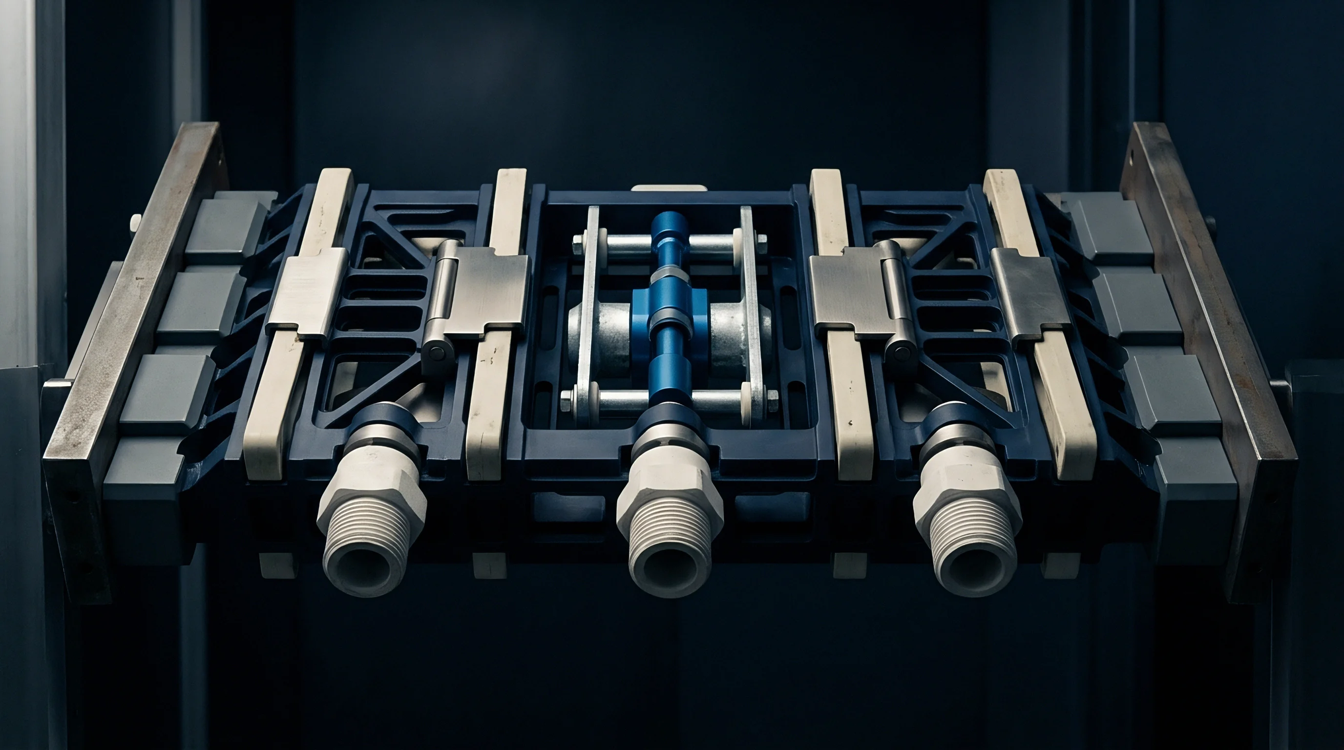
Supply line inductance limits high-speed current delivery, while local decoupling capacitors absorb instantaneous rail fluctuations.

Trace
Physical conductor properties dictate high-frequency transmission behavior across fine-pitch interconnect networks. Standard copper dual-damascene processing reaches physical limits below twenty-two nanometer metal pitch. Bulk copper has a resistivity of 1.7 microhm-centimeters, but thin-film surface scattering and grain boundary reflections push effective resistivity beyond fifteen microhm-centimeters in sub-five nanometer trenches.
Tantalum or ruthenium diffusion barriers take up a fixed thickness of one to two nanometers per trench, stealing up to thirty percent of the conductive area. The restricted copper cross section drives up line resistance, amplifying local IR drops during transient switching cycles.
Alternative metals bypass barrier scaling bottlenecks in the lowest interconnect tiers. Pure ruthenium and molybdenum have shorter electron mean free paths than copper, enabling narrow lines to avoid the steep resistivity rise seen in scaled copper wiring. Ruthenium can be deposited without a separate diffusion barrier, leaving more usable conductor area inside tight high-aspect-ratio trenches.
Switching to these metals lowers total interconnect resistance at sub-twenty nanometer dimensions, dampening local transient IR drops when multiple signals fire at once.
A thirty percent reduction in lower-tier via resistance recovers six percent of total transient margin across critical timing loops.

Which Interconnect Metrics Dictate Real Transient Margins?
Via resistance is the largest single electrical obstacle in scaled metallization stacks. Standard copper vias at five nanometer contact boundaries measure between fifty and two hundred ohms per cut. Signals traveling up from nanosheet gate terminals through M0, M1, and intermediate distribution layers pass through stacked via arrays that add hundreds of ohms of cumulative series impedance.
High-frequency transient currents moving through these vertical transitions suffer immediate IR drops that eat directly into functional noise margins.
Backside power delivery changes this geometry by routing power and ground grids along the rear face of the thinned silicon wafer. Buried power rails etched alongside nanosheet devices connect directly to backside metal layers through nano-through-silicon vias. Separating supply lines from frontside signal wiring gives signal traces more routing room and reduces parasitic capacitive coupling, while power networks benefit from thick backside copper planes measuring hundreds of nanometers across.

Metallurgy Shifts from Copper to Alternative Conductors
Changing conductor materials alters physical reliability alongside electrical performance. High current densities in ultra-scaled copper wires drive electromigration voiding, leading to open-circuit failures over prolonged operation. Ruthenium has a higher cohesive energy and melting point than copper, pushing its electromigration activation energy above two electron-volts.
That higher current density tolerance permits greater root-mean-square switching currents without running the risk of void formation under sustained rail ripple.
| Interconnect Layer | Conductor Metallurgy | Drawn Pitch (nm) | Line Resistance (Ω/µm) | Transient Drop Factor |
|---|---|---|---|---|
| Frontside M0 | Copper with Ru Liner | 21.0 | 145 | 0.82 |
| Frontside M0 Alternative | Direct Ruthenium | 21.0 | 88 | 0.54 |
| Frontside M1 | Copper with TaN Liner | 22.0 | 120 | 0.74 |
| Buried Power Rail | Ruthenium | 28.0 | 42 | 0.31 |
| Backside Power Metal 1 | Thick Copper Damascene | 100.0 | 1.2 | 0.04 |
Integrating alternative metals requires substantial changes in dry etch processing. Ruthenium forms no volatile byproducts under standard halogen plasma chemistries, forcing etchers to use elevated wafer temperatures and aggressive oxygen gas mixtures. Selectivity against underlying dielectric layers is narrow, making profile control critical; any sidewall taper narrows the cross-sectional area, cutting into expected resistance gains and leaving the wire vulnerable to transient drops.
Internal layout design rules are often assumed to account for via resistance growth, leaving customer timing margins to absorb whatever transient drop remains.


Foundry
Silicon foundries rely on rigid electronic design automation kits to define noise signoff rules for advanced tapeouts. Sourcing custom accelerators or proprietary wireless silicon requires careful review of those underlying signoff assumptions. Foundries balance yield against advertised speed targets and frequently depend on vectorless static rail analysis for tapeout signoff.
But static tools average power over full clock cycles, hiding the sub-nanosecond transient droop events that cause timing failures during peak workloads.
Vector-based transient power integrity simulation is necessary to catch high-frequency noise violations in sub-five nanometer designs. Sourcing teams must define detailed stimulus patterns that trigger worst-case simultaneous switching across execution pipelines, memory interfaces, and high-speed SerDes links. Building thorough vector sets takes hundreds of engineering hours, adding to non-recurring engineering costs and pushing back tapeout schedules by four to eight weeks.
Skipping this step often leaves teams discovering functional instability only during wafer sort.
Signoff methodology declarations determine whether silicon failures under peak logic load trigger foundry compensation or internal engineering write-downs.

Will Backside Metallization Shift Foundry Tapeout Signoff?
Building chips with backside power requires wafer-to-wafer or wafer-to-carrier bonding. Thinning the device wafer down to several hundred nanometers reveals buried power connections, but it creates mechanical fragility and serious thermal challenges. Silicon conducts heat much better than back-end dielectric materials do.
Replacing the silicon substrate with multi-layer backside dielectric stacks traps heat in active nanosheet channels, and that rise in operating temperature increases metal line resistance, shrinking noise margins faster than room-temperature models predict.
Signoff rule decks are expanding to include coupled electro-thermal analysis alongside transient rail extraction. Engineering teams must confirm that the PDK models self-heating inside buried power rails and nano-through-silicon vias. Parasitic extraction yields massive netlists with billions of distributed RLC elements; running dynamic simulations on datasets that size takes substantial compute clusters and solver licenses, pushing tool costs past two hundred thousand dollars per seat.

Signoff Vector Completeness and Package Parasitics
Package design directly affects transient noise on the die. Advanced chiplet layouts use silicon interposers or high-density redistribution layers to connect processing tiles. Micro-bumps joining die pads to the substrate carry parasitic inductances from five to twenty-five picohenries apiece.
Sourcing contracts need to state clearly who owns the co-design of the complete power delivery network across the die, interposer, and board-level voltage regulators.
- Transient stimulus vector sets delivered in standard value change dump formats must capture multi-cycle peak current demands across all synchronous clock domains.
- Parasitic extraction netlists built from 3D field solver extractions of back-end and backside power layers allow accurate transient resonance mapping.
- Package touchstone models with multi-port S-parameters capture inductive and capacitive behavior up to the twentieth harmonic of core clock frequencies.
- Electro-thermal impedance matrices link local device power dissipation to conductor temperature increases, updating line resistance during dynamic simulation.
Standard foundry contracts include defect density warranties, but they explicitly exclude timing failures caused by vector-dependent transient voltage collapse.

Variance
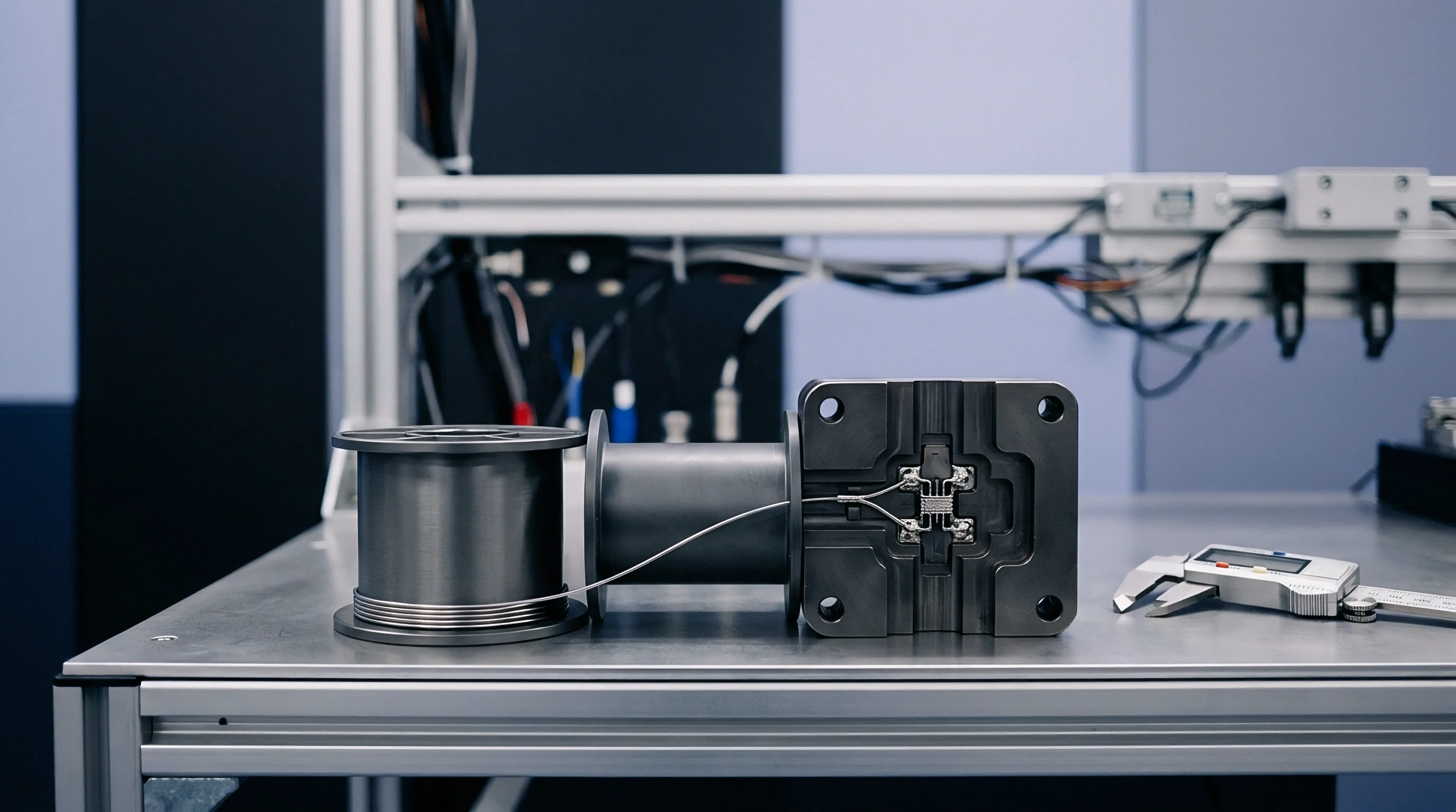
Fabrication tolerances cause noticeable physical variation across sub-five nanometer runs. Critical line dimensions vary by plus or minus ten percent across a reticle field, while trench depths shift depending on local pattern density. Narrowing a twenty-nanometer ruthenium trace by ten percent increases line resistance by more than twenty percent because of surface scattering.
Slow-slow process corners combine minimum transistor drive current with maximum line resistance, reducing transient noise margins to zero even at nominal supply voltage.
Random dopant fluctuations and line-edge roughness create threshold voltage mismatches between neighboring nanosheet devices. Standard cells with low drive strengths show wide variations in propagation delay when exposed to temporary rail droop. Clock distribution trees suffer spatial skew when buffers on one branch undergo local inductive droop while buffers on an adjacent branch see full supply voltage.
Skew shifts above fifteen picoseconds cause setup violations in gigahertz logic blocks, forcing clock speed downgrades.

Thermal Inversion and Device Aging Degradation
Operating sub-five nanometer nodes at low voltages changes traditional thermal behavior. Near one volt, higher temperatures degrade channel mobility and slow gate transitions. Near 0.7 volts, however, rising temperature lowers threshold voltage, offsetting mobility loss and speeding up switching.
This shift complicates transient noise analysis: a sudden supply drop at high operating temperatures can instantly push a logic block out of thermal inversion compensation, adding interconnect RC delay on top of increased gate delay.
Bias temperature instability and hot carrier injection shift transistor thresholds over years of use. Transconductance can drop by ten to fifteen percent after five years of continuous operation, reducing drive current and slowing the discharge of parasitic interconnect capacitance. At the same time, atomic migration in lower vias increases vertical resistance.
This combined degradation eats away initial design margins, eventually triggering bit errors when high-frequency switching spikes occur in aging hardware.

Worked Allocation for Transient Noise Budgets
Building a workable transient noise budget requires accounting for every millivolt across multiple noise mechanisms. Consider a three-nanometer logic macro running on a nominal 0.700-volt supply. If the lower stability limit for register retention is 0.580 volts, the total noise budget is 120 millivolts.
All electrical noise sources must fit inside this budget during worst-case switching scenarios.
| Noise Mechanism | Frontside PDN Baseline (mV) | Backside PDN Upgrade (mV) | Design Control Mechanism |
|---|---|---|---|
| Static DC IR Drop | 28 | 8 | Metal Grid Sizing |
| High-Frequency L di/dt Bounce | 45 | 22 | On-Die MIM Capacitors |
| Capacitive Signal Crosstalk | 22 | 14 | Routing Shielding Rules |
| Thermal Inversion Shift | 12 | 8 | Floorplan Power Spreading |
| Silicon Aging Margin | 10 | 8 | Guardband Clock Derating |
| Unallocated Reserve | 3 | 60 | Yield Recovery Buffer |
The frontside power delivery architecture consumes 117 millivolts of the 120-millivolt allocation, leaving a reserve of just three millivolts. Layout congestion or unexpected via voids will easily push voltage drops past the 120-millivolt limit and cause field crashes. Moving to backside power delivery reduces both static and high-frequency drops, reclaiming sixty millivolts of headroom.
That extra margin supports higher clock speeds or denser logic without risking transient timing failures.
Verified empirical models are still lacking to predict how local thermal hotspots accelerate via electromigration under high-frequency rail ripple over ten operating years.


Invoice
Financial risk in sub-five nanometer development depends heavily on how responsibilities are divided between vendor and buyer. Turnkey contracts put implementation risk on the module vendor, who delivers fully tested silicon against a defined functional specification. That model comes with high unit cost premiums ~ individual processor modules run from two hundred to eight hundred dollars depending on die size and packaging complexity ~ and the supplier retains ownership of internal layout files, mask records, and power signoff reports.
Semi-custom arrangements split engineering tasks between in-house teams and third-party IP vendors. The buyer licenses block IP, registers, and buses, but handles floorplanning and power grid design internally. Mask sets for sub-five nanometer tapeouts cost upwards of fifteen million dollars, making layout errors extremely expensive.
When silicon fails under transient power spikes, contract disputes quickly surface over whether the licensed IP had flaws or the customer’s power grid failed to hold rail voltage.
Transfer packages lacking vector-dependent signoff simulations fail second-source qualification audits and trap the buyer within the original vendor’s production facilities.
Commercial Scope Lines for Sub-Five Nanometer Mask Sets
The design transfer package is the main asset generated by development spending. Moving production to a second foundry requires a complete signoff dossier: GDSII or OASIS layout data, parasitic extraction decks, dynamic simulation testbenches, and ATE test vector scripts. Without clear contractual ownership of custom library cells and power network layouts, a buyer cannot easily port the design to another supplier.
Tooling amortization dictates early cash flow during production scaling. Vendors often offer lower NRE fees in exchange for guaranteed multi-thousand-wafer volume commitments over twenty-four months. But if transient noise issues drag functional wafer yields below eighty percent, unit costs rise quickly as the vendor triggers price adjustment clauses.
Teams manage this risk by tying NRE payouts to explicit milestones, including dynamic rail stability audits on silicon characterization wafers.

Deliverables Package for Turnkey and Semi-Custom Handover
The statement of work sets the technical deliverables required before releasing mass-production tooling funds. A well-written SOW clarifies who handles post-silicon validation, who debugs jitter caused by high-frequency rail bounce, and who pays for mask revisions if timing closure fails. Redesigning power networks post-tapeout runs up to five hundred dollars an hour in engineering time, which burns through contingency budgets quickly.
Omitting transient noise signoff terms during module procurement risks silent data corruption across production lots and leaves the buyer covering the cost of mask revisions.