Standard Thermal Soak Protocols for Relocated Precision Scale Assembly
Precision scale relocation demands staged unpowered thermal soaking and powered warm-up to eliminate chassis gradients before performing span calibration.


Chamber
A temperature differential of 1.8 Kelvin across an aluminum load-receiver flexure displaces zero-point reading by thirty-two scale divisions on a 0.01 milligram EMFR weigh cell before stabilization starts. That physical displacement occurs because raw thermal expansion moves the mechanical fulcrum long before internal sensors detect ambient equilibrium. When transport crates move from an unheated freight dock into a climate-controlled cleanroom, the scale assembly undergoes non-uniform volumetric contraction or expansion.
Outer housing panels adjust within thirty minutes, cast metal sub-chassis structures take hours, and heavy core magnets require even longer.
Unpacking an unconditioned balance exposes cold mechanical linkages to warm, humid ambient air. Condensation forms in micro-droplets along internal flexure blades, shifting tare weight and altering the dielectric properties of capacitive position detectors. The instrument enclosure functions as an internal micro-climate.
Air currents circulate inside draft shields whenever enclosure wall temperatures differ from the internal weighing pan by more than 0.2 Kelvin, producing convection cells that exert persistent vertical drag on the pan.
Enclosure air reaches thermal equilibrium hours before the internal magnet core stops expanding.
Thermal time constants depend directly on material density and assembly mass. The reference design for high-resolution electromagnetic force restoration balances packs substantial thermal inertia into small footprints to resist rapid ambient changes. That same mass delays operational readiness during facility transfers.
A technician who powers up an instrument immediately upon uncrating forces electric current through cold copper coil windings. The resulting localized internal heating gradient clashes directly with external ambient stabilization, distorting zero-return performance for an entire working shift.
| Scale Resolution Class | Chassis Mass (kg) | Unpowered Soak Time (h) | Powered Warm-Up Time (h) | Total Equilibration Window (h) |
|---|---|---|---|---|
| Microbalance (0.001 mg) | 12.5 | 12.0 | 6.0 | 18.0 |
| Semi-Microbalance (0.01 mg) | 8.0 | 6.0 | 4.0 | 10.0 |
| Analytical Balance (0.1 mg) | 6.0 | 3.0 | 2.0 | 5.0 |
| Precision Balance (1.0 mg) | 4.5 | 1.5 | 1.0 | 2.5 |

Air Boundary Staging
Enclosed weighing volumes trap pockets of warm gas during transfer between facilities. Staging protocols isolate the crated instrument within the destination room boundary prior to opening packaging seals. Vapor-barrier bags remain intact during the primary equalization phase, preventing cleanroom moisture from condensing on bare metal tooling surfaces.
The scale assembly sheds thermal gradients through passive conduction through container walls while sealed against airborne contaminants.
Draft shields remain closed throughout the unpowered soak sequence. Opening side doors introduces cross-draft velocities that disrupt the passive settling rate of the flexure linkages. Technicians maintain closed glass partitions to allow internal structural components to normalize through conduction rather than turbulent convective exchange.
Premature exposure destroys thermal symmetry across the mechanical lever arms.
Calibration errors during site acceptance stem predominantly from facility air conditioning cycles rather than missing soak periods.

Plinth
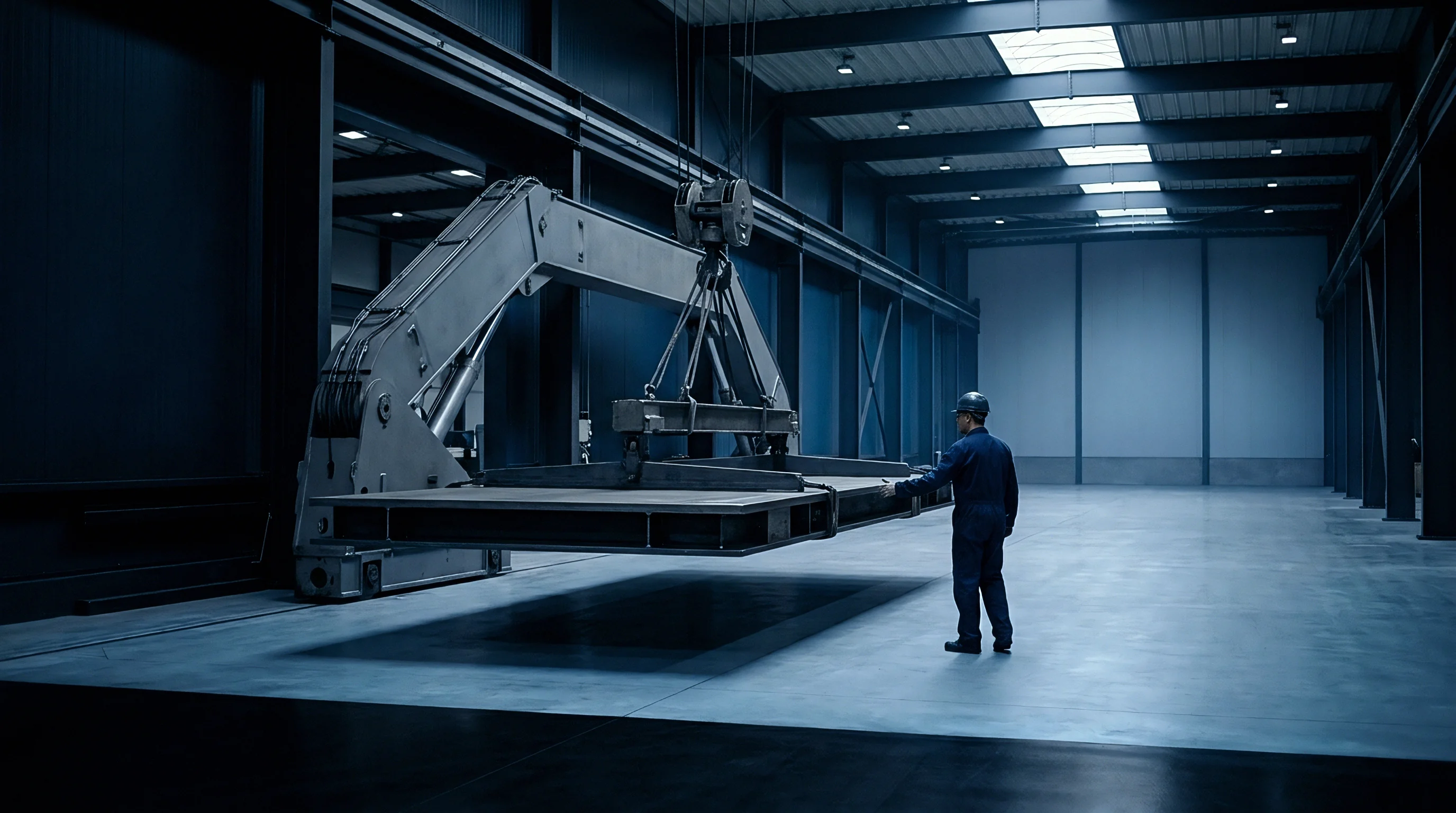
Heavy granite bases absorb ambient vibrations while functioning as long-duration heat sinks. The thermal mass of a two-hundred-kilogram stone bench stabilizes the laboratory environment against rapid room air swings, yet it introduces a massive conduction sink beneath the scale feet. When an analytical balance arrives at a new facility, placing the chassis onto a cold plinth creates a steep vertical thermal gradient across the assembly feet: the base plate cools rapidly while the upper draft shield remains at room ambient, setting up stresses where expansion coefficients diverge.
Unequal contraction between the front leveling screws and the rear pivot anchor tilts the weighing cell off its perpendicular gravity axis. Micro-radian angular tilts register as apparent mass shifts on electromagnetic force restoration transducers. The internal flexure system experiences asymmetrical stress, shifting mechanical zero beyond the compensation authority of internal tare algorithms.
Isolating the scale feet with tuned elastomeric pads reduces conductive thermal shock, though excessive compliance compromises mechanical rigidity.
Thick stone supports balance rapid shop-floor temperature swings through sheer mechanical delay.
Mechanical Substructure Damping
Solid support blocks dictate the rate at which an instrument sheds conductive energy. Leveling mechanisms transfer structural heat directly into the lower casting of the weigh cell, establishing thermal conduits through threaded stainless steel posts. When facility managers relocate an assembly between rooms with different plinth surface temperatures, the lower chassis twists along the transverse plane, binding internal linkages while knife-edge pivots and flexure strips bow under differential expansion between the aluminum balance case and the stone table surface.
Relocating an instrument without characterizing plinth temperature introduces mechanical distortion modes across the weighing core:
- Flexure hinge warping alters the geometric alignment of the balance mechanism.
- Permanent magnet flux decline alters the electromagnetic force restoration constant at a rate of 350 parts per million per Kelvin.
- Analog front end offset introduces continuous baseline wander across high-precision analog-to-digital converters during gradient dissipation.
- Draft shield convection generates localized vertical air currents that exert aerodynamic force against the weighing pan.
Skipping structural temperature equalization leads to systematic weighing errors that invalidate production batch records across subsequent shifts.


Drift
Unstable readings appear immediately when an analytical sensor enters a new room environment. Thermal drift manifests as a continuous directional wander in the zero-point register, driven by thermal relaxation in spring elements and temperature-dependent resistance shifts inside analog front-end electronics. Monolithic weigh cells cut from single aluminum billets mitigate joint hysteresis, though bulk thermal expansion still warps the metal geometry.

Can Monitored Dissipation Curves Confirm Mechanical Stability?
Real-time recording of zero-point displacement reveals whether internal stresses have relaxed. Technicians record raw balance counts at regular intervals without zeroing or taring the instrument. Plotted over time, unconditioned scales trace logarithmic decay curves that match classical Fourier heat conduction models.
Drift rates exceed ten scale divisions per hour during initial unboxing, flattening only as core metal components approach ambient equilibrium ~ an underlying settling process that digital filters frequently obscure.
Euramet calibration guide cg-18 recommends a minimum equilibration allowance of one hour per Kelvin of temperature differential between transit and laboratory environments for Class I balances. That recommendation rests on empirical multi-laboratory trials conducted on fifty analytical weighing units, assuming passive room air circulation around unenclosed housings. The recommendation shifts upward when scales incorporate heavy sub-chassis shielding or custom IP65 washdown enclosures.
A sixty-kilogram industrial checkweigher requires significantly longer passive rest periods to dissipate internal crate heat than an unenclosed laboratory microbalance.
Telescope mount builders observe an identical physical constraint when moving multi-ton glass mirror blanks from preparation shops to mount plinths in high-altitude observatories, waiting through long nocturnal soak windows before optical alignment can begin. Weigh cells face the identical physics at milligram scale, where unrelaxed internal heat continues to drive localized air currents.
| Transducer Architecture | Stabilization State | Mean Temperature Gradient (K/h) | Zero Drift Rate (div/h) | Settling Status |
|---|---|---|---|---|
| Electromagnetic Force Restoration | Unpowered Bench Rest | 1.20 | 18.4 | Transient Mechanical Warp |
| Electromagnetic Force Restoration | Powered Circuit Active | 0.15 | 2.1 | Approaching Thermal Stability |
| Monolithic Quartz Tuning Fork | Unpowered Bench Rest | 1.20 | 6.2 | Structural Temperature Lag |
| Monolithic Quartz Tuning Fork | Powered Circuit Active | 0.10 | 0.8 | Complete Equilibrium |
| Foil Strain Gauge Bridge | Unpowered Bench Rest | 1.20 | 11.0 | Elastomer Bed Creep |
| Foil Strain Gauge Bridge | Powered Circuit Active | 0.25 | 3.5 | Resistive Balance Attained |
Published literature offers thin documentation for ultra-microbalance settling times when units cross seasonal climate bands inside air cargo containers. A twenty-four-hour unpowered soak represents standard cleanroom practice for microgram-resolution hardware, though rigorous thermal modelling to defend that exact window remains unavailable in published metrology dossiers. Cleanroom integrators mitigate that uncertainty by executing automated overnight zero-drift logging, verifying that baseline slope drops below two micro-divisions per hour before releasing the unit for span calibration.
Zero-point drift on an energized analytical cell declines below 0.05 milligrams per hour only after twenty-four hours of constant mains connection at stable ambient temperature.
Field commissioning teams execute a rigid procedural staging sequence to guarantee repeatable thermal equilibration across cleanroom transfers:
- Transit receipt logging records internal container temperature profiles before technicians breach external vapor barriers.
- Gross unpowered soaking allows heavy metal castings to reach ambient thermal equilibrium with room air while avoiding internal circuit heating.
- Powered circuit excitation energizes electromagnetic restoration coils, display drivers, and power supplies to form steady internal thermal plumes.
- Sequential zero inspection tracks balance baseline drift across consecutive twenty-minute intervals to evaluate mechanical stability before span adjustment.
Whether low-frequency oscillations in zero-point registers originate from atmospheric pressure fluctuations or microscopic core expansion remains an open debate among metrology engineers.

Hysteresis
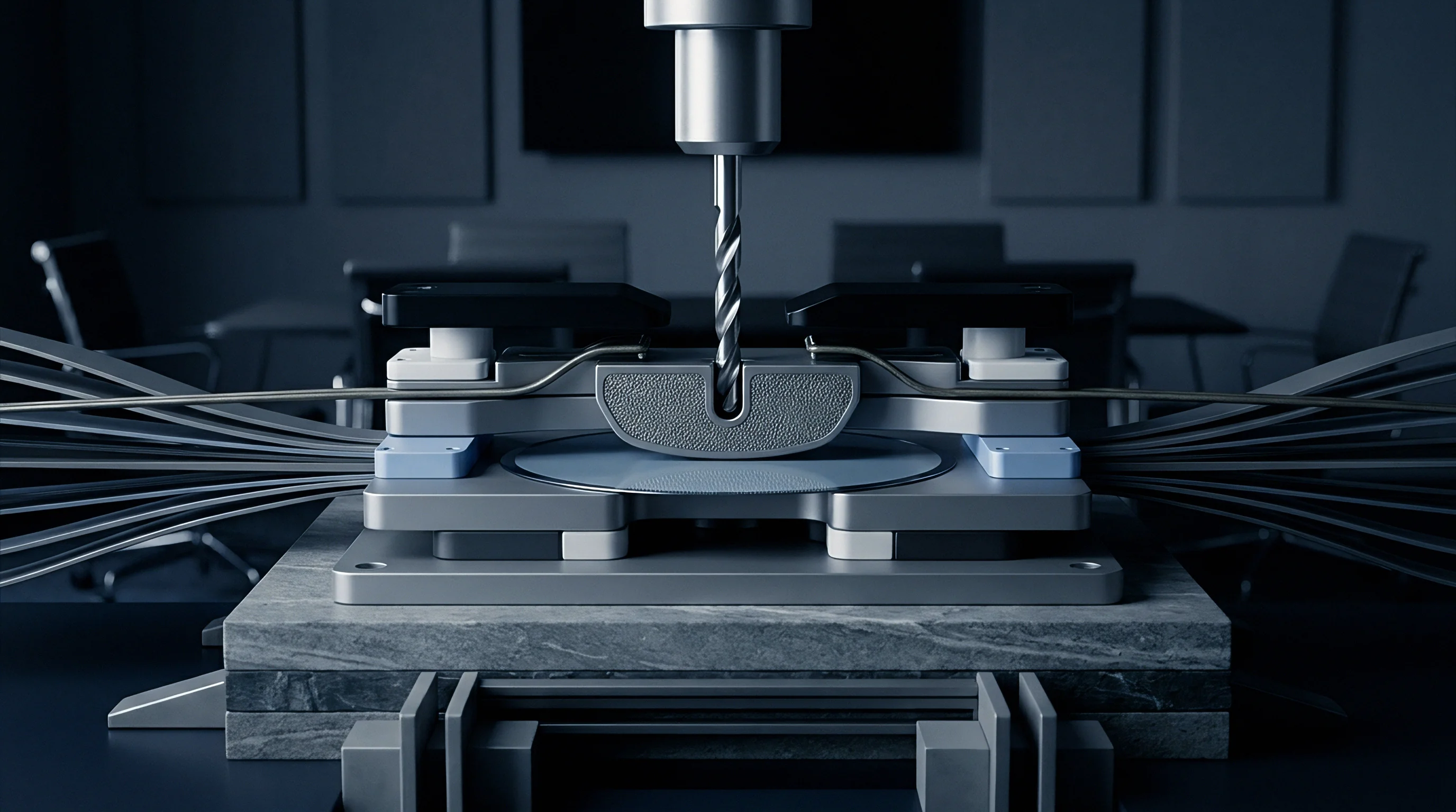
Spring alloys within the suspension mechanism retain physical memory of thermal distortion. Beryllium copper flexures and Ni-Span-C compensation links undergo thermo-elastic creep when subjected to rapid temperature changes, shifting their elasticity modulus temporarily. A scale calibrated while thermal hysteresis persists inside the flexure leaf displays non-linear span errors across its weighing range, alongside continuous downward baseline creep.

Will Power Cycling Reset Transferred Zero Points?
Switching off internal circuitry disrupts the local thermal equilibrium established during operation. When technicians cycle power on a recently relocated weigh cell, the internal electronics drop from forty degrees Celsius to ambient room temperature, initiating a fresh contraction cycle across the sensor board. Reapplying power introduces localized heating around voltage regulators and driver transistors that alters magnetic core flux.
Firmware-driven tare algorithms often mask true mechanical creep from the operator. Many commercial balances feature auto-zero tracking routines that continuously zero out slow baseline wander below 0.5 verification scale intervals. This digital filtering tricks the technician into assuming the assembly has achieved thermal soak completion.
Disabling software zero-tracking during integration reveals the raw baseline trajectory, exposing unrelaxed mechanical strain inside the load receiver linkage.
Evaluating dual-sensor compensation schemes on custom-integrated weighing assemblies involves auditing specific mechanical and electronic parameters:
- Fulcrum thermistor bonding places measurement sensors directly against structural flexures rather than peripheral chassis frames.
- Correction polynomial execution applies compensation coefficients across the full operating range without clipping raw transducer inputs.
- Transport latch verification identifies plastic strain on internal overload stops before technicians initiate thermal balancing cycles.
- Zero tracking suppression disables automatic baseline averaging so technicians can inspect true raw mechanical creep during soak cycles.
Under OIML R76 clause 3.9.2, an instrument undergoing ambient variation demonstrates zero return within half a verification scale interval, which compels suppliers to bolt sensor elements directly against the flexure linkage.

Schedule
Time allocation on a commissioning timeline directly governs the accuracy of initial verification. In pharmaceutical cleanrooms and semiconductor packaging lines, project managers face extreme commercial pressure to compress equipment installation schedules. Every hour spent soaking an analytical scale on a granite bench delays line bring-up and postpones production validation.
Specifying the integration tier determines who pays for soak-induced downtime and where testing responsibility rests. Sourcing a white-label complete scale shifts testing to standard end-user procedures, but leaves the buyer vulnerable to factory burn-in shortcuts. Sourcing an uncalibrated weigh cell module on a semi-custom statement of work demands dedicated non-recurring engineering expenditure for environmental test chambers and automated drift-logging fixtures.
The factory delivers hardware; the buyer engineers the thermal regime.
Handover agreements lacking defined thermal equilibration windows leave commissioning contractors paying unabsorbed line-idle penalties.
Tooling and testing responsibilities diverge sharply across integration models:
| Integration Level | Thermal Calibration Ownership | Line Downtime Responsibility | NRE Tooling Allocation (USD) | Handover Deliverables |
|---|---|---|---|---|
| White-Label Complete Scale | Original Equipment Manufacturer | Factory Integrator | 0 | Certificate of Conformity, Basic User Guide |
| Turnkey Weigh Cell Module | Shared Boundary by Interface | Split by Schedule Clause | 15,000 to 35,000 | Interface Control Drawing, Factory Test Dossier |
| Semi-Custom Precision Assembly | Purchaser Engineering Team | Purchasing Facility | 60,000 to 140,000 | Source Firmware, Mechanical CAD, Sensor Compensation Maps |
| Methods note: Data reflects median contractual allocations observed across cross-border precision automation transfers. | ||||
Semi-custom weighing assemblies require comprehensive design transfer packages containing raw temperature-coefficient matrices, sensor calibration source files, and mechanical assembly drawings with fastener torque specifications. Omitting thermal soak parameters from the statement of work guarantees schedule overruns during line commissioning. Factory acceptance tests conducted at a supplier site in Shenzhen at twenty-eight degrees Celsius cannot be replicated in a Zurich cleanroom at twenty degrees Celsius without full thermal stabilization, especially since reference mass standards exhibit their own thermal lag.
Allow the weighing mechanism to rest until the display stabilizes, then wait an equal duration before touching the calibration mass.