LoRa Duty Cycle Ceilings That Decide Payload Frequency
LoRa duty cycle ceilings restrict packet frequency by limiting hourly transmission airtime, forcing trade-offs between spreading factor, payload size, and battery life.


Airtime
A Semtech SX1262 transceiver configured for a 24-byte sensor payload at Spreading Factor 10, using a 125 kHz channel bandwidth and Coding Rate 4/5, occupies sub-GHz spectrum for 370.7 milliseconds. Drop that packet down to Spreading Factor 7 and the duration falls to 56.6 milliseconds; push it to Spreading Factor 12 and the burst expands to 1482.8 milliseconds. Radio physics ties chirp rate directly to receiver sensitivity, forcing every byte transmitted over a LoRa physical layer into an explicit temporal budget.
Continuous radio radiation creates a physical footprint in milliseconds, bounded by statutory channel ceilings that limit how often a device can key its transmitter.
Calculating exact Time on Air (ToA) is central to throughput engineering in non-cellular license-exempt bands. The LoRa physical layer uses Chirp Spread Spectrum (CSS) modulation, ramping carrier frequency linearly across a specified channel bandwidth. Ramp speed depends on the chosen Spreading Factor (SF), which dictates the bits encoded per symbol.
A Spreading Factor of SFN uses 2N chips per symbol. Higher spreading factors trade longer symbol durations for increased processing gain and better receiver sensitivity. Symbol duration (Ts) equals 2SF divided by channel bandwidth (BW).
At 125 kHz bandwidth, an SF7 symbol lasts 1.024 milliseconds, whereas an SF12 symbol takes 32.768 milliseconds.
Total packet transmission time breaks down into preamble duration and payload duration. The preamble acts as a synchronization sequence for the receiving gateway radio, letting phase-locked loops lock onto the incoming frequency sequence. Preamble duration (Tpreamble) is calculated by multiplying the preamble symbol count (Npreamble, typically 8 symbols) plus 4.25 synchronization symbols by Ts. For an 8-symbol preamble, that leaves a mandatory preamble overhead of 12.25 symbols before any user data goes out.
Calculating payload symbol duration brings in more variables: explicit or implicit header modes, coding rates, and low data rate optimization mechanisms. Explicit header mode adds physical header symbols containing payload length, coding rate, and an optional 16-bit cyclic redundancy check (CRC). Coding rates (CR) add forward error correction, scaling payload size by 4/5, 4/6, 4/7, or 4/8.
When symbol duration exceeds 16 milliseconds ~ as it always does at SF11 and SF12 under 125 kHz bandwidth ~ the physical layer must enable Low Data Rate Optimization (LDRO). This setting drops effective bits per symbol by two to maintain clock drift immunity over longer packets, further inflating total symbol count.

Symbol Duration and Modulation Mechanics
Field measurements show that expanding payload length hits discrete step-function thresholds in symbol allocation rather than a smooth curve. Because payload bits pack into whole symbols, adding one byte to an 11-byte payload can force the physical layer to allocate a full extra symbol, adding tens or hundreds of milliseconds to airtime depending on the configured spreading factor.
| Spreading Factor | Symbol Duration (ms) | 10-Byte Payload ToA (ms) | 50-Byte Payload ToA (ms) | 200-Byte Payload ToA (ms) | Receiver Sensitivity (dBm) |
|---|---|---|---|---|---|
| SF7 | 1.024 | 41.22 | 102.66 | 328.00 | -123.0 |
| SF8 | 2.048 | 72.19 | 174.59 | 563.71 | -126.0 |
| SF9 | 4.096 | 123.90 | 308.22 | 1004.54 | -129.0 |
| SF10 | 8.192 | 226.30 | 554.00 | 1823.74 | -132.0 |
| SF11 | 16.384 | 476.16 | 1131.52 | 3654.66 | -134.5 |
| SF12 | 32.768 | 870.40 | 2148.35 | 6981.63 | -137.0 |
Data rate selection dictates the link margin. Running at SF12 provides a 14 dB sensitivity advantage over SF7, effectively doubling line-of-sight range in open space or penetrating three extra reinforced concrete floors indoors. As shown in the measurements, that 14 dB gain comes at the cost of a 21-fold increase in spectral occupancy for a 10-byte payload, jumping from 41.22 milliseconds to 870.40 milliseconds.
For a 200-byte payload, SF12 requires nearly 7 seconds of unbroken transmission.
Every millisecond on air consumes battery energy at the node while blocking other transmitters on that frequency. When evaluating radio links, engineers often overestimate network capacity by relying on raw bitrate calculations. LoRa CSS is an ultra-narrowband, highly redundant modulation scheme built for link resilience rather than high throughput.
Any design sending frequent, large sensor updates has to operate at low spreading factors to avoid transmission backoff lockouts under regional spectrum rules.
Whether future spectrum harmonization will unify sub-GHz airtime rules or leave hardware platforms navigating fragmented regional duty cycle regimes remains an open structural uncertainty.


Grid
Spectrum authorities partition sub-GHz frequencies into rigid channel grids, coupling channel allocations with strict operational limits. A module shipped into the European Single Market must comply with ETSI standard EN 300 220-1. In the United States, the Federal Communications Commission (FCC) regulates the same equipment under FCC Part 15 Subpart C, section 15.247.
These statutory frameworks differ entirely in philosophy, enforcement, and packet limits. A firmware architecture engineered for North American continuous frequency hopping will violate European channel occupancy rules within seconds.
European sub-GHz allocations sit primarily in the 863 MHz to 870 MHz ISM band. ETSI applies a strict duty cycle ceiling across these frequencies, defined as cumulative transmission time over a rolling one-hour window. Sub-band g1 (868.0 MHz to 868.6 MHz), the primary telemetry band, enforces a 1.0 percent duty cycle limit at maximum output (+14 dBm / 25 mW ERP).
Sub-band g2 (868.7 MHz to 869.2 MHz) restricts transmissions further to a 0.1 percent ceiling. Sub-band g3 (869.4 MHz to 869.65 MHz) permits power up to +27 dBm (500 mW ERP) and a 10 percent duty cycle, though high-power gateways and smart meters heavily congest this slice.

European Duty Cycles and Continental Ceilings
Under ETSI rules, an end-device has a fixed envelope of airtime that cannot be exceeded regardless of operational urgency. A 1.0 percent duty cycle gives a device 36 seconds of cumulative transmission per hour. A 0.1 percent duty cycle cuts that allowance to 3.6 seconds per hour.
Because the observation window slides, firmware cannot dump its 36-second allocation in one burst at the start of an hour and start transmitting again at the next hour without violating the rolling 60-minute window.
Regulatory duty cycle compliance must be calculated against the highest Spreading Factor the link budget can fall back to under maximum path loss conditions.
By contrast, the US FCC framework does not impose percentage-based hourly duty cycle limits on the 902 MHz to 928 MHz ISM band. Instead, the FCC enforces channel hopping parameters and transmission duration ceilings under Part 15.247. For systems using 125 kHz LoRa bandwidths, the transmitter must hop pseudo-randomly across at least 50 discrete channels, with maximum dwell time on any single channel capped at 400 milliseconds within a 20-second period.
If channel bandwidth expands to 500 kHz, the system can operate under digital modulation rules ~ dropping the 50-channel requirement while capping peak output power at +30 dBm (1 Watt) with a maximum power spectral density of +8 dBm in any 3 kHz band.
This structural difference presents clear design choices for global hardware platforms. In the US, a node can transmit hundreds of short payloads per hour as long as individual channel occupancy stays under 400 milliseconds per hop sequence. In Europe, that same device will lock its radio after reaching the 36-second cumulative threshold, no matter how many channels it hops across within g1.
| Region / Standard | Frequency Band | Primary Mechanism | Ceiling Parameter | Maximum Transmit Power |
|---|---|---|---|---|
| Europe (ETSI EN 300 220) | 868.0 ~ 868.6 MHz (g1) | Duty Cycle | 1.0% (36s/hour) | +14 dBm ERP |
| Europe (ETSI EN 300 220) | 868.7 ~ 869.2 MHz (g2) | Duty Cycle | 0.1% (3.6s/hour) | +14 dBm ERP |
| Europe (ETSI EN 300 220) | 869.4 ~ 869.65 MHz (g3) | Duty Cycle | 10.0% (360s/hour) | +27 dBm ERP |
| United States (FCC Part 15) | 902.0 ~ 928.0 MHz (125 kHz) | Dwell Time / FHSS | 400 ms per channel / 20s | +30 dBm conducted |
| United States (FCC Part 15) | 902.0 ~ 928.0 MHz (500 kHz) | DTS Modulation | Peak PSD limit (+8 dBm/3kHz) | +30 dBm conducted |
| Asia-Pacific (AS923) | 920.0 ~ 925.0 MHz | LBT / Duty Cycle | LBT RSSI < -80 dBm or 1% DC | +16 dBm EIRP (varies) |
Asian jurisdictions using the AS923 channel plan take a hybrid approach. Countries like Japan require Listen Before Talk (LBT) mechanisms at the physical layer. Before keying the power amplifier, the transceiver performs Channel Activity Detection (CAD) or a clear channel assessment for a minimum duration (typically 5 milliseconds).
If the Received Signal Strength Indicator (RSSI) exceeds a threshold like -80 dBm, the channel is treated as busy, forcing the node into a randomized exponential backoff before checking again. Where LBT is mandated, authorities sometimes relax duty cycle percentages, though polling the channel repeatedly adds battery overhead.
Managing multi-region SKUs requires firmware abstraction layers that enforce regional spectrum rules based on provisioning settings or GPS geofencing. If this abstraction fails, non-compliance risks regulatory fines, customs seizures, or gateway node revocation.
Designing cross-border products ultimately means designing down to the lowest common denominator across target markets.


Arithmetic
Translating regulatory duty cycles into sensor uplink schedules takes direct mathematical modeling. Payload size, Spreading Factor, and statutory ceilings intersect to limit maximum transmission frequency. A smart water meter reporting 16 bytes of usage data every 15 minutes presents a completely different operational load than an industrial vibration sensor pushing 128 bytes of FFT summary data every 60 seconds.
Take an asset tracker operating in Europe within the ETSI 868 MHz g1 sub-band, bound by a 1.0 percent duty cycle allowance (36,000 milliseconds of airtime per rolling hour). The tracker formats telemetry into a 32-byte binary payload containing location coordinates, battery status, and sensor alerts. Adding LoRaWAN protocol overhead (8 bytes explicit physical header, 13 bytes MAC header, payload MIC, and 12.25 preamble symbols) brings physical layer frame size to 53 bytes.
Near a gateway under optimal conditions, Adaptive Data Rate (ADR) assigns the node Spreading Factor 7 at 125 kHz bandwidth. The resulting ToA for a single 53-byte frame is 102.66 milliseconds. Dividing the 36,000-millisecond hourly allowance by 102.66 milliseconds yields a theoretical maximum of 350 transmissions per hour ~ roughly one uplink every 10.2 seconds.
At SF7, payload frequency easily covers real-time tracking.

How Does Payload Expansion Truncate Daily Uplink Count?
Field link conditions are rarely static. As a tracking vehicle enters a concrete loading bay or moves toward the edge of coverage, the network MAC layer initiates ADR decay. The gateway registers falling Signal-to-Noise Ratios (SNR) and instructs the node to step down its data rate to compensate for path loss.
Uplink capacity drops off sharply as Spreading Factor scales upward to preserve the link.
- Initial baseline state at SF7 ~ ToA reaches 102.66 ms, consuming 0.285 percent of the 36-second hourly allowance per transmission for up to 350 uplinks per hour.
- First step attenuation to SF9 ~ ToA expands to 308.22 ms, consuming 0.856 percent of the hourly allowance per frame and reducing maximum frequency to 116 uplinks per hour.
- Moderate obstruction at SF10 ~ ToA scales to 554.00 ms, consuming 1.538 percent of the hourly budget per burst and capping transmission count at 64 uplinks per hour.
- Severe degradation at SF11 ~ ToA climbs to 1131.52 ms with Low Data Rate Optimization active, consuming 3.143 percent of the hourly budget and limiting the node to 31 transmissions per hour.
- Extreme edge loss at SF12 ~ ToA surges to 2148.35 ms, consuming 5.967 percent of the hourly allowance in a single frame and capping payload capacity at 16 transmissions per hour (one packet every 225 seconds).
Dropping from SF7 to SF11 in a shielded laboratory vault cuts daily payload capacity by 42 percent. When a device falls to SF12, an application requesting updates every 60 seconds will attempt 60 transmissions per hour. But the duty cycle tracker in the LoRaWAN MAC stack intercepts transmission requests after the 16th packet, silently dropping payloads or returning radio-busy flags for the rest of the hour.
A hardware supply agreement must specify maximum allowable packet loss caused by MAC-layer duty cycle lockouts under degraded spreading factors.
Payload packing optimization gives software engineers a way to work within duty cycle boundaries. Sending raw ASCII or JSON across sub-GHz links wastes limited airtime. Packing a 120-byte string payload into a 14-byte bit field drops ToA at SF10 from 1187.8 milliseconds down to 258.0 milliseconds, instantly quadrupling the node’s hourly uplink budget without touching the physical link.
Every byte added to an uplink payload carries a compounding airtime cost that limits transmission frequency across all spreading factors.
Service agreements between system integrators and industrial customers frequently embed performance guarantees on reporting frequency. ISO/IEC 25010 metrics applied to IoT procurement contracts typically mandate a 99.5 percent telemetry delivery rate at fixed 5-minute intervals. If a contract fails to account for regulatory duty cycle ceilings under worst-case SF12 propagation, the vendor becomes liable for missing delivery windows that radio regulations make illegal to meet.

Bench
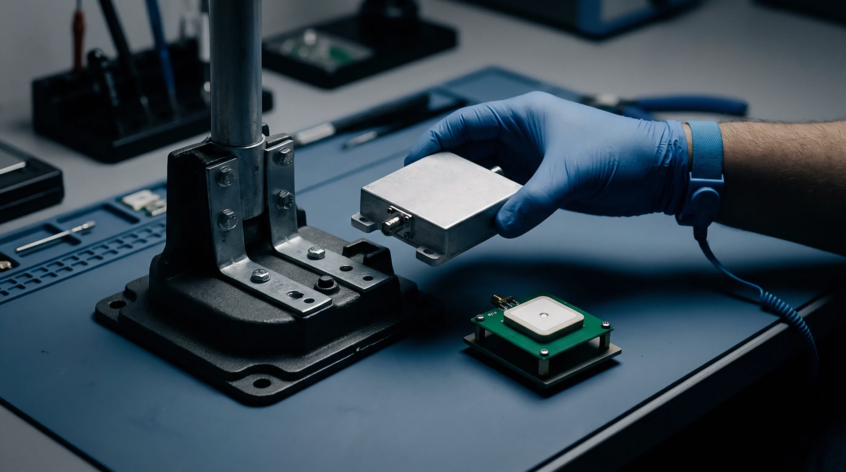
Verifying duty cycle compliance and actual airtime takes physical measurement on the test bench. Datasheet tables and software simulations leave gaps: oscillator tolerances, firmware execution latencies, cold-start synthesizer lock delays, and undocumented MAC stack backoff algorithms all alter a transmission’s actual timing.
A verification bench typically places a high-speed current shunt monitor or Nordic Power Profiler Kit II in series with the device under test (DUT) supply rail, alongside a sub-GHz spectrum analyzer or software-defined radio (SDR) tuned to the carrier frequency. The current monitor gives microsecond time-domain visibility into power state transitions, exposing exact preamble start times, power amplifier ramp rates, payload duration, RX1 and RX2 receive window delays, and sleep transitions.
A current profile trace shows distinct phase signatures during an uplink. On triggering a transmission, the microcontroller wakes from deep sleep with a brief current pulse. The crystal oscillator initializes, followed by the PLL synthesizer locking onto the carrier frequency.
The RF front-end keys up, causing a sharp jump in supply current (for instance, 118 mA at +22 dBm output from an SX1262). Transmit continues for the exact duration of the calculated ToA. After transmitting, the transceiver drops into low-power idle for 1000 milliseconds before opening the RX1 receive window to listen for downlinks, drawing around 5.3 mA while checking the receive symbol.

Firmware Duty-Cycle Tracking Mechanics
Firmware stack flaws are a common cause of field failures and regulatory non-compliance. The MAC layer has to maintain an accurate duty cycle accumulator in non-volatile or power-retained memory. Each time the radio finishes transmitting a packet of duration TToA on sub-band k with regulatory duty cycle ceiling DCk, the stack must calculate the mandatory off-time (Toff) before transmitting again on that sub-band:
Toff = (TToA / DCk) – TToA
For a 200-millisecond transmission on a 1.0 percent duty cycle band (DCk = 0.01), mandatory off-time equals (200 / 0.01) – 200 = 19,800 milliseconds (19.8 seconds). During this 19.8-second lockout, the MAC stack must reject any application request to transmit on sub-band k. Advanced stacks avoid total lockout by hopping to an available channel in a different sub-band (switching from g1 to g2, for instance), assuming the accumulator for that band has budget remaining.
Validation teams frequently uncover firmware defects during bench testing. Common failure modes that break spectral compliance or cause data starvation include:
- Accumulator Reset on Power Cycle ~ Storing the duty cycle counter in volatile SRAM without backing it up before a reset means an application or watchdog reboot clears the accumulator, letting the device immediately re-transmit and breach statutory limits.
- Channel Hopping Allocation Asymmetry ~ Failing to track duty cycle limits per band and applying a single global timer across 1% and 0.1% sub-bands leads to early lockout on clean channels or illegal over-transmission on restricted ones.
- Unbounded Join Request Loops ~ On gateway disconnects, continuous LoRaWAN Join Request retries at maximum power and SF12 consume over 1.4 seconds per attempt. Rapid retry loops exhaust the hourly duty cycle allowance in two minutes, locking the device out for the remaining 58 minutes.
- Clock Drift Calibration Failure ~ The internal 32.768 kHz RC oscillator drifts under temperature extremes, causing firmware to underestimate elapsed time and prematurely release transmit blocks.
Before committing to volume production, hardware sourcing teams should evaluate module vendors against a radio qualification checklist:
- Hardware Stack Audit ~ Verify that the module integrates a qualified MAC stack (such as Semtech LBM or a certified LoRaWAN stack) with independent lab validation for ETSI EN 300 220 and FCC Part 15.247.
- Non-Volatile Duty Cycle Retention ~ Confirm through source audit or bench tests that duty cycle state variables persist through microsecond brownouts and forced resets.
- Thermal Drift Bounds ~ Validate that crystal oscillator tolerances (TCXO implementation) maintain symbol timing accuracy within +/- 1.5 ppm across the full operating range (-40°C to +85°C).
- Downlink Airtime Management ~ Confirm that network server gateway profiles enforce downlink duty cycle tracking to prevent gateway channel exhaustion during heavy acknowledgment or Class C multicast traffic.
A bench test log showing compliance at 25°C ambient temperature provides zero guarantee of duty cycle accuracy at 60°C without a compensated crystal oscillator.
Unexpected field lockouts are often attributed to gateway downlink congestion rather than internal stack timer bugs.

Ledger
Engineering decisions driven by duty cycle ceilings map directly onto the landed-cost ledger. Spectrum limits dictate payload frequency and payload sizes, but they also shape battery chemistry choices, maintenance intervals, gateway density, and overall connectivity economics.
Battery selection is a major capital cost sensitive to packet airtime. Sub-GHz hardware widely relies on Lithium Thionyl Chloride (LiSOCl2) cells ~ like the ER14505 AA or ER34615 D cell ~ for multi-year operation. LiSOCl2 offers high energy density but passivates when idling under light loads, requiring high-current pulses (100 mA to 150 mA) to break the passivation layer and key the power amplifier.
When poor coverage or link margin pushes a device to high spreading factors (SF11 or SF12), those high-current pulses stretch from tens of milliseconds to several seconds. Prolonged high-current pulses risk voltage dips below the microcontroller reset threshold and degrade battery capacity far faster than self-discharge models predict.
Calculating real operational lifespan and battery cost for a sensor deployment means building airtime current profiles into the power budget. Sizing a primary battery for a 10-year target under ETSI g1 constraints requires the following steps:
- Determine total daily sleep charge by multiplying deep sleep current (such as 1.8 microamps) by 86,400 seconds and converting microamp-seconds to milliamp-hours.
- Calculate active frame charge by measuring peak transmit current, RX receive window current, and active microcontroller processing time, multiplying each phase by its duration in seconds.
- Multiply single-frame active charge consumption by the target daily transmission frequency (such as 24 uplinks per day) to establish baseline daily milliamp-hour demand.
- Apply the Spreading Factor penalty multiplier from propagation models, scaling active charge by worst-case airtime at cell edges.
- Sum daily sleep charge and worst-case active charge to get total daily energy consumption in milliamp-hours.
- Multiply daily consumption by 3,650 days for 10-year baseline capacity requirements.
- Add a 20 percent battery self-discharge allowance plus a 15 percent margin for temperature extremes and passivation losses to determine final minimum battery rating.
A node transmitting 50 bytes at SF7 needs roughly 1.2 Ah over 10 years, easily handled by a single ER14505 cell costing $1.40 in volume. If that node operates at SF12 because of a distant gateway, expanded ToA multiplies energy consumption per transmission by 20. Reaching a 10-year lifespan at SF12 requires a large ER34615 D cell costing $6.80, quadrupling battery costs and enlarging the enclosure.
| Operating Parameter | Spreading Factor 7 | Spreading Factor 10 | Spreading Factor 12 |
|---|---|---|---|
| Payload Size / Bandwidth | 50 Bytes / 125 kHz | 50 Bytes / 125 kHz | 50 Bytes / 125 kHz |
| Packet Airtime (ToA) | 102.66 ms | 554.00 ms | 2148.35 ms |
| Max Hourly Transmissions (1% DC) | 350 | 64 | 16 |
| Energy per Transmission (mAs) | 12.1 mAs | 65.3 mAs | 253.5 mAs |
| 10-Yr Battery Requirement (24 uplinks/day) | 1.15 Ah (ER14505) | 2.85 Ah (ER18505) | 7.20 Ah (ER34615) |
| Estimated Cell Unit Hardware Cost | $1.40 | $3.10 | $6.80 |
| Landed Message Cost Ratio (Relative) | 1.0x (Baseline) | 5.4x Overhead | 21.0x Overhead |
Deploying private gateways offers a direct trade-off. Increasing gateway density reduces distance to edge nodes, letting Adaptive Data Rate algorithms keep devices at SF7 or SF8. An enterprise deploying 10,000 smart utility meters can install 20 extra outdoor gateways at $1,200 each ($24,000 total) or equip 10,000 nodes with oversized SF12-capable batteries at an extra $5.40 per unit ($54,000 in BOM costs).
The capital cost of adding indoor gateway density is fully recovered by the bill-of-materials savings realized across high-density node deployments operating at lowest spreading factors.
When payload frequency outstrips sub-GHz LoRa duty cycle caps, alternative protocols enter the picture. Moving to cellular IoT options like LTE-M (eMTC) or NB-IoT eliminates statutory airtime limits, allowing frequent updates regardless of spreading factor. But that shift trades license-exempt operation for recurring SIM subscriptions, carrier certification fees, higher sleep currents, and carrier approvals.
Evaluating total cost of ownership across sub-GHz deployments requires modeling battery aging, regulatory airtime limits, and infrastructure density together as an integrated system rather than isolated line items.