Mitigating Receiver Desensitization in Embedded Cellular Devices
Mitigating receiver desense demands isolating baseband clock harmonics, damping power rail switching ringing, and enforcing board layout ground plane symmetry.


Floor
A cellular transceiver soldered to a high-density system board experiences an immediate elevation of its thermal noise base. Conducted sensitivity measurements executed inside a screened enclosure via coaxial cable establish the silicon benchmark, often reaching -102 dBm on LTE Band 20 or -104 dBm on Band 28 under standard 10 MHz reference channel configurations. The moment the RF port transitions to an internal patch, monopole, or inverted-F antenna, the receiver noise floor rises.
Internal digital clocks, memory address buses, switched-mode inductors, and serial display lines radiate electromagnetic fields directly into the antenna structure. This elevation degrades Total Isotropic Sensitivity, rendering the device blind to distant base station transmissions.
Every decibel of receiver noise figure increase strips link budget directly from the cell edge. When a battery-operated utility sensor operates with a 6 dB desensitization penalty on LTE-M Band 12, the operational coverage footprint contracts by more than half under free-space propagation conditions. The modem negotiates this compromised downlink by requesting higher transmit repetitions, draining stored cell charge through extended power amplifier duty cycles.
Radiated platform noise degrades receiver performance through several distinct mechanisms across standard frequency allocations.
| Aggressor Noise Source | Harmonic Frequency Range | Impacted 3GPP Cellular Band | Coupling Path Mechanism | Typical Desense Impact |
|---|---|---|---|---|
| Buck Converter Ringing (2.2 MHz switch) | 700 MHz to 960 MHz | Band 5, Band 8, Band 12, Band 20 | Inductor stray field to antenna trace | 4.5 dB to 11.0 dB |
| SPI / QSPI Flash Clock (104 MHz fundamental) | 728 MHz (7th), 832 MHz (8th) | Band 13, Band 28 downlink | Single-ended trace loop radiation | 3.0 dB to 8.5 dB |
| USB 2.0 High-Speed Bus (480 Mbps differential) | 1930 MHz to 2170 MHz | Band 1, Band 2, Band 4, Band 66 | Differential skew to common-mode conversion | 2.0 dB to 6.0 dB |
| MIPI DSI Display Data (450 MHz clock) | 1800 MHz (4th), 2250 MHz (5th) | Band 3, Band 7 downlink | Flex cable aperture radiation | 5.0 dB to 14.0 dB |
System designers frequently identify the degradation late during carrier acceptance screening. The module functions predictably on open development carriers. Board stacking, housing compression, and the addition of peripheral sensors then flood the receiver input with correlated broadband and narrowband spectral peaks.
Cellular carriers impose rigorous certification thresholds through standards bodies such as PTCRB and GCF, where a device failing Total Isotropic Sensitivity limits by a fraction of a decibel faces commercial rejection.
Conducted sensitivity of -104.5 dBm drops to an effective radiated sensitivity of -93.2 dBm when a 104 MHz bus harmonic strikes the 782 MHz Band 13 downlink center channel.
The gap between conducted silicon performance and enclosed radiated capability governs operational survivability. Mitigating this degradation requires diagnosing energy paths before copper commit occurs. Missing the certification mark forces board respins, tooling delays, and expensive laboratory retesting cycles that drain product launch reserves.
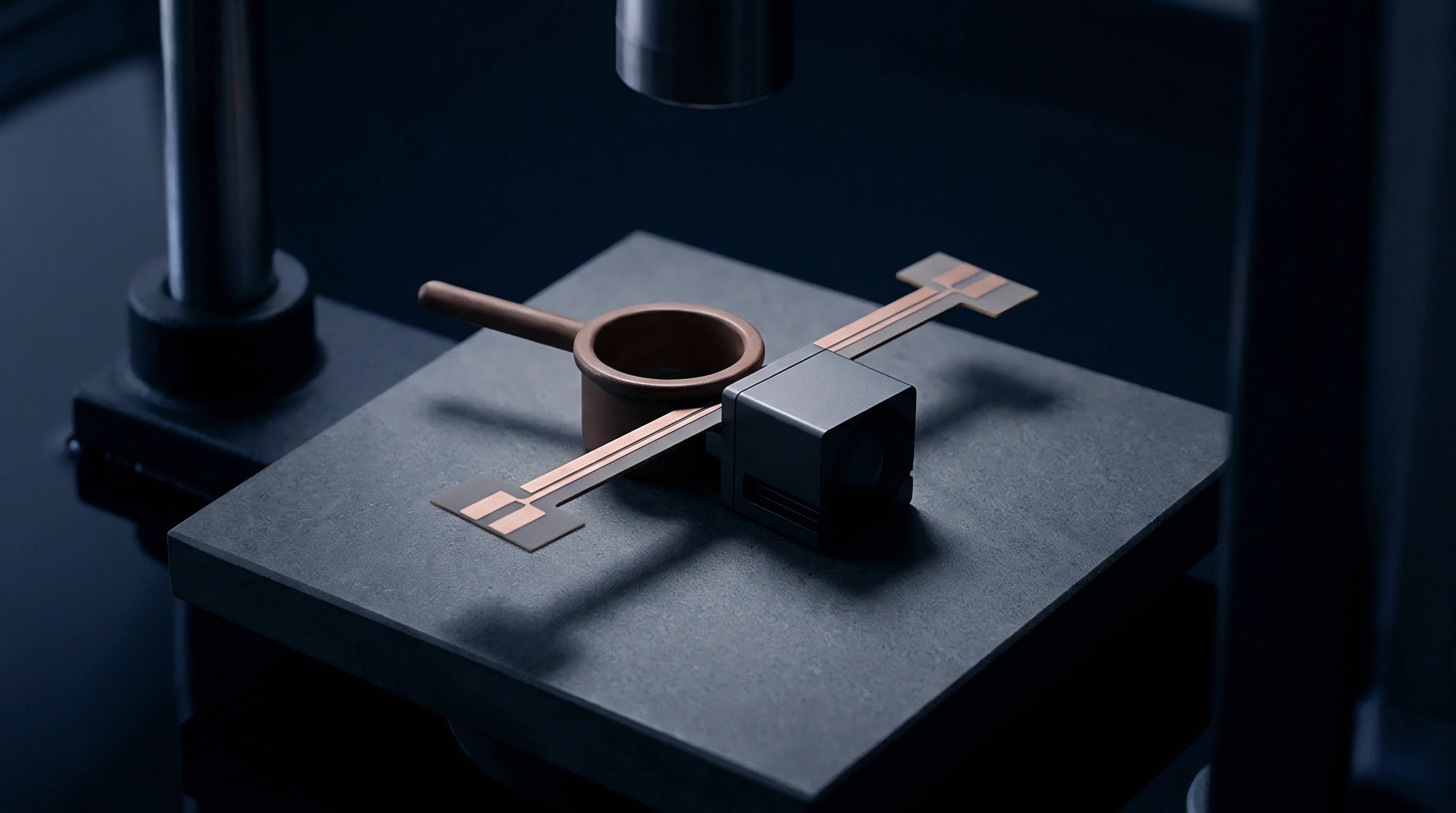
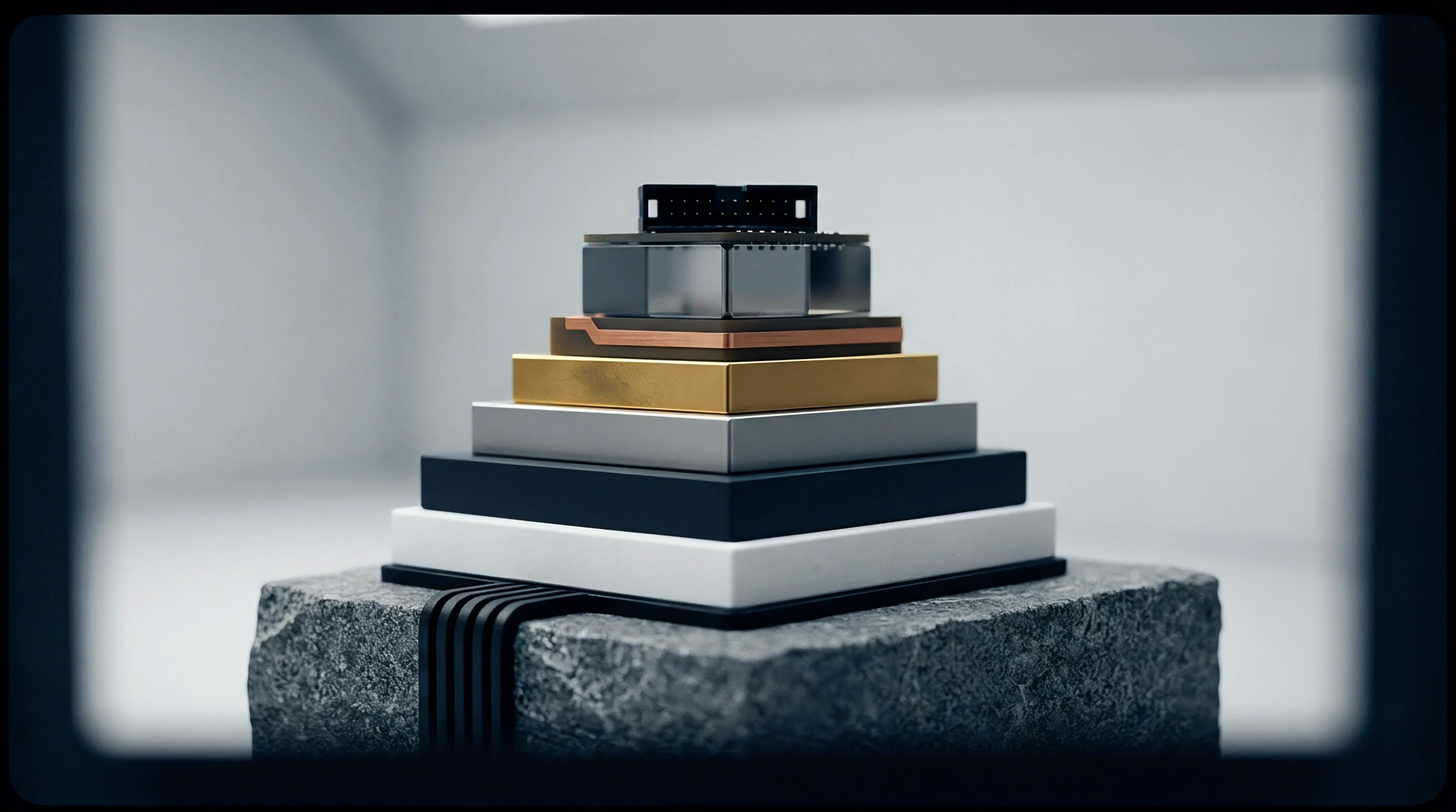
Shield
Containing radiated electromagnetic fields demands continuous conductive barriers placed between high-speed logic circuits and RF front-end components. Metal shield cans formed from nickel-silver, tin-plated copper, or stainless steel intercept radiated electric and magnetic near-field components before they strike internal antenna elements. Solder-attached frames paired with removable lid assemblies allow physical access during bench diagnostics while providing low-impedance ground returns around noisy baseband processing silicon.
Solid metal coverage alone fails when aperture leakage permits RF currents to exit enclosure seams.

Aperture Radiation and Seam Inductance
Slot antennas form unintentionally along the mechanical interface between a shielding frame and its snap-on cover. Radio frequency currents flowing across the interior surface encounter gaps between mechanical retention dimples. When the spacing between ground contact points exceeds one-twentieth of the cellular downlink wavelength, the seam functions as an efficient radiator.
At 2.1 GHz, a slot dimension of 7 millimeters creates measurable aperture leakage directly into nearby trace antennas. Continuous solder attachment along the complete perimeter of the shield wall eliminates these mechanical slots.

Why Do Switched Inductors Pollute Low Bands?
Magnetic field coupling dominates the sub-gigahertz spectrum where cellular low bands operate. Switch-mode power converters rely on energy storage inductors carrying rapid current transitions up to several amperes. Unshielded wire-wound inductors shed magnetic dipole flux that penetrates thin aluminum or standard thin copper plating without significant attenuation.
The magnetic skin depth in non-ferrous metals at 750 MHz allows magnetic fields to induce circulating currents on the outer faces of shield enclosures, where they re-radiate into cellular antennas.
- Unshielded Inductor Placement near the main antenna feeds magnetic energy straight into receiver matching networks, bypassing conducted trace filters entirely.
- Aperture Openings For Thermal Relief exceed physical dimensions of two millimeters, permitting high-frequency harmonics from application processor cores to scatter outward.
- Flex Cable Penetrations cross through perimeter shielding without capacitive filtering, acting as unintended dipole radiator arms that carry baseband currents outside the can.
- Single-Point Chassis Grounding introduces high loop inductance, transforming the entire metal frame into an elevated potential radiator relative to the main ground reference.
Interposing composite lossy magnetic absorber sheets inside the shielding cavity suppresses cavity resonance modes. High-permeability elastomeric absorbers attenuate electromagnetic reflections between 800 MHz and 3 GHz, converting trapped RF energy into minute quantities of heat. Suppressing internal cavity resonances prevents standing waves from amplifying specific processor clock harmonics.
Ground plane geometry establishes the counterpoise for embedded antenna structures. When high-speed ground returns share conductive copper space with RF ground returns, common-impedance coupling injects baseband noise voltages directly into the antenna feedpoint. Splitting ground planes with narrow cutouts creates slot radiators.
Continuous, unbroken inner ground reference layers provide minimum-impedance mirror paths for RF return currents.
Thick dielectric separation between signal layers and reference planes increases field confinement. Thin prepreg layers under high-speed traces force the electromagnetic field tightly into the dielectric substrate. This layout discipline contracts the fringing fields that would otherwise illuminate the internal cellular antenna structure.
Mechanical tolerances dictate long-term shielding performance. Contact resistance across raw mechanical interfaces climbs over time through atmospheric oxidation and mechanical vibration cycles.
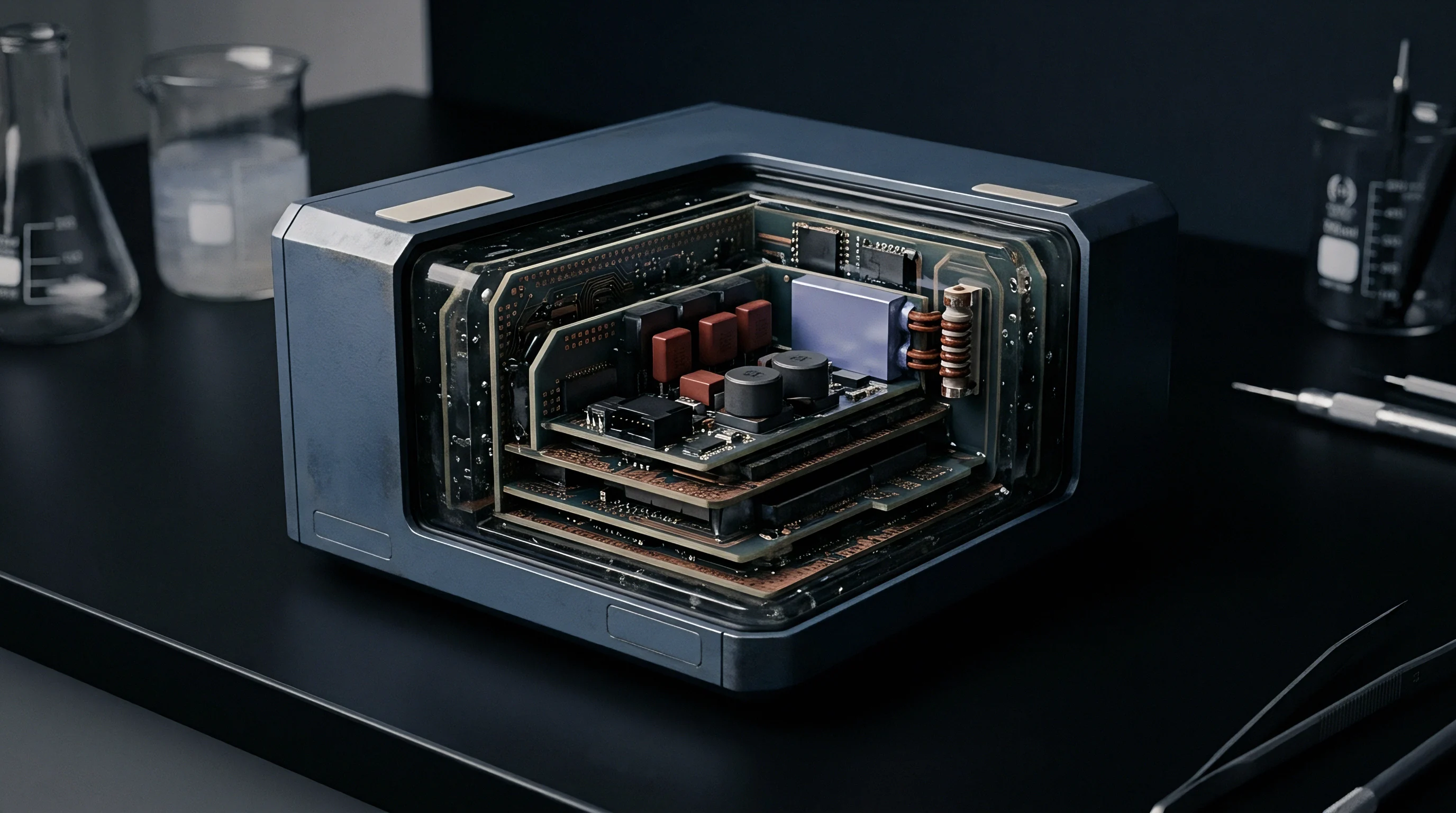
Choke
Conducted noise propagates across power distribution networks directly into sensitive cellular RF transceivers. Low-dropout regulators and multi-channel power management units exhibit limited power supply rejection ratios above several hundred kilohertz. High-frequency current pulses generated by memory arrays and processor switching cores travel along continuous copper supply planes, entering transceiver supply rails.
Passive inductive filtering halts this energy transfer along DC distribution paths.
| Filter Topology | Passband Insertion Loss | Rejection at 700-960 MHz | Rejection at 1710-2170 MHz | DC Current Rating |
|---|---|---|---|---|
| Ferrite Bead (1000 Ohm at 100 MHz) | 0.15 dB | 22 dB to 31 dB | 14 dB to 20 dB | 1.2 A |
| Common-Mode Choke (90 Ohm differential) | 0.40 dB | 18 dB to 26 dB | 25 dB to 38 dB | 400 mA |
| Feedthrough Capacitor (1000 pF) | 0.05 dB | 35 dB to 48 dB | 40 dB to 52 dB | 2.0 A |
| Pi-Filter (10 pF – Ferrite – 100 pF) | 0.25 dB | 38 dB to 54 dB | 32 dB to 44 dB | 800 mA |
Selecting decoupling capacitors demands precise identification of series self-resonant frequencies. Standard ceramic dielectric capacitors cease providing capacitive bypass functionality above their series resonance point. A 100 pF 0402 capacitor exhibits low impedance near 800 MHz, creating an effective bypass path for low-band noise.
A parallel 10 pF capacitor addresses noise near 1.9 GHz. Combining multiple values in tight geometric clusters maintains low impedance across cellular downlinks.
Filter components placed more than three millimeters away from a semiconductor pin permit surface traces to harvest ambient RF noise through trace inductance.
Traces leaving power converter stages require systematic conducted isolation before reaching sensitive logic. Tracking down conductive noise currents follows an orderly physical isolation sequence during initial prototype verification.
- Identify all switched-mode power converter output rails using a high-bandwidth oscilloscope paired with a passive near-field magnetic probe.
- Measure broadband spectral amplitude on battery and regulated rail connections using a spectrum analyzer across the 600 MHz to 2700 MHz envelope.
- Insert surface-mount ferrite beads exhibiting peak resistive impedance within target cellular receive bands directly adjacent to the switching diodes.
- Place low-equivalent-series-resistance decoupling capacitors immediately at the power entrance pins of the cellular module.
- Connect shield grounds directly to the primary system ground plane using densely spaced vias located less than two millimeters apart.
Power rail noise also couples into phase-locked loop synthesizers within the cellular baseband silicon. Synthesizer phase noise broadens receive mixing skirts, allowing strong adjacent-channel blockers to mask weak incoming downlink carriers. Clean supply lines preserve reciprocal mixing margins within internal downconversion stages.
The vendor states that reference board designs inherently pass all carrier sensitivity checks without supplementary filtering hardware.


Firmware
Modifying clock dynamics through software routines provides immediate relief when hardware redesign is impossible. Fixed clock frequencies generate static, high-amplitude harmonic spikes at integer multiples of their fundamental operating frequencies. When an integer multiple lands precisely within an active 3GPP channel bandwidth, receiver desensitization occurs instantly.
Modulating the clock frequency distributes spectral energy across a broader bandwidth, lowering the peak power spectral density below the cellular receiver noise floor.

Spread Spectrum Clock Generation
Modern microcontrollers, display controllers, and dynamic memory interfaces incorporate internal phase-locked loops capable of spread spectrum modulation. Introducing a center-spread or down-spread frequency modulation between 0.5 percent and 2.0 percent scatters harmonic peaks. Instead of a sharp, high-energy spectral spike falling directly inside an LTE channel raster, the harmonic appears as elevated broadband noise with a significantly reduced peak value.
This reduction frequently recovers between 3 dB and 7 dB of lost receive margin.

Will Dynamic Clock Shifting Prevent Carrier Drops?
Altering the core oscillator frequency during specific operational states prevents harmonic collisions with active cellular channels. A microcontroller running at 120 MHz generates an eighth harmonic at 960 MHz, overlapping the upper boundary of Band 8. Shifting the system clock dynamically to 116 MHz moves that eighth harmonic down to 928 MHz, clearing the active channel.
Firmware tracks the active cellular operating band by polling the modem via standard AT interface commands.
- Band Interrogation Commands read the current cellular carrier channel number during connection establishment routines.
- Dynamic Prescaler Adjustments alter internal bus clock dividers to move harmonic multiples outside the requested downlink resource block allocations.
- Per-Channel Frequency Tables define permissible clock settings for every deployed global cellular frequency channel.
- Bus Throttling Routines suspend external memory access over QSPI or SPI interfaces while cellular paging reception occurs.
Synchronizing external peripheral communications with cellular modem time-division frames avoids simultaneous high-speed switching during weak signal reception. Under LTE-M and NB-IoT protocols, the module enters predictable discontinuous reception windows. Firmware suspends non-urgent sensor transactions, display refreshes, and flash memory writes during these active downlink listening periods.
Radiated digital noise ceases while the modem receiver processes incoming frames.
Section 7.3 of 3GPP TS 36.101 dictates that cellular terminals maintain specified minimum reference sensitivity under all concurrent device functional operations.
Firmware-based mitigation avoids physical component changes. Software control introduces timing jitter and processing latency into time-critical peripheral drivers. Balancing processing bandwidth against radio reception clarity demands precise execution profiling across the operating lifespan of the embedded device.
Carrier lab certification profiles demand documented compliance under standard 3GPP TS 36.521-1 test clauses, penalizing devices that rely on non-standard baseband halts during active communication sessions.

Chamber
Anechoic measurement represents the definitive benchmark for evaluating internal noise mitigation. Near-field scanning tools identify localized hot spots across circuit board surfaces, revealing problematic traces and leaking enclosures. These localized scans fail to predict far-field interference patterns.
Placing the complete, battery-powered embedded device inside a calibrated over-the-air anechoic chamber establishes true Total Isotropic Sensitivity values across all targeted carrier bands.
During anechoic characterization, the cellular communication tester establishes an active signaling connection with the device under test. The turntable rotates through 360 degrees in azimuth while the measurement antenna sweeps elevation angles across dual orthogonal polarizations. Integrating sensitivity measurements over a full spherical pattern yields the spatial sensitivity metric mandated by network operators.
| Cellular Frequency Band | Conducted Reference Sensitivity | CTIA Operator Pass Limit | Unmitigated Device TIS | Mitigated Final Device TIS |
|---|---|---|---|---|
| LTE Band 12 (700 MHz Low) | -104.5 | -99.0 | -91.5 | -100.8 |
| LTE Band 20 (800 MHz Low) | -103.5 | -98.5 | -92.0 | -100.2 |
| LTE Band 5 (850 MHz Low) | -104.0 | -99.5 | -93.8 | -101.4 |
| LTE Band 3 (1800 MHz Mid) | -102.5 | -97.0 | -92.4 | -98.6 |
| LTE Band 7 (2600 MHz High) | -101.0 | -95.0 | -91.0 | -96.5 |
Performance variations between low-band and high-band frequencies reflect differing physical mechanisms. Low-band channels below 1 GHz suffer heavily from chassis ground plane currents because the entire circuit board functions as an active counterpoise element. Mid-band and high-band performance depends predominantly on direct trace-to-antenna near-field illumination and connector slot leakage.
Mitigating one portion of the frequency spectrum leaves other bands vulnerable if board resonances shift.
Evaluating link margin in field deployments confirms bench findings. A device exhibiting a 3 dB TIS degradation requires twice the base station transmitter power to maintain equal data throughput rates at the cell periphery. In rural deployments where base stations operate at maximum power limits, that 3 dB loss severs connectivity entirely, stranding remote telemetry hardware.
Antenna matching components placed within the reactive near field distort phase profiles and convert common-mode board currents directly into receiver front-end noise.
Field environments introduce external variables including physical ground planes, metallic mounting structures, and human body proximity. These external conductors detune antenna resonance frequencies, sliding the antenna response curve across the spectrum. A harmonic previously sitting benignly in an antenna null suddenly aligns with the shifted antenna peak.
Evaluating mitigation integrity must account for real-world detuning conditions.
Tracking the source of intermittent receiver packet loss exposes an unresolved question regarding whether unpredictable multi-carrier intermodulation products generated within passive structural metals can be fully simulated during early layout modeling.