Selecting Wi-Fi Modules for Dense High-Interference Industrial Environments
Industrial Wi-Fi module selection demands matching OFDM guard intervals to measured hall delay spread while isolating 5 GHz spatial streams from local noise.


Echo

Delay Spread and Metallic Reflection Dynamics
Industrial assembly halls with galvanized steel framing, gantry cranes, concrete floors, and dense machinery create severe multipath environments for RF signals. When a transceiver transmits an 802.11 frame, the wave bounces off metal surfaces and splits across hundreds of indirect paths. These multipath signals arrive at the receiving antenna out of phase, producing localized nulls where signal strength can drop by 30 dB over a distance of just six centimeters.
Selecting a radio module for these environments depends on how effectively its demodulation pipeline manages that delayed signal energy.
The time gap between the direct line-of-sight signal and the final significant reflection defines the root-mean-square delay spread. Commercial settings usually measure between 30 and 100 nanoseconds, but heavy industrial facilities routinely range from 250 to 900 nanoseconds. Standard Orthogonal Frequency Division Multiplexing symbols rely on a guard interval to prevent inter-symbol interference.
When multipath reflections outlast that guard window, residual energy from the prior symbol leaks into the fast Fourier transform window, corrupting subcarrier phase relationships. The receiver then fails to decode the modulation coding scheme, triggering steady cyclic redundancy check frame drops despite bench readings showing strong signal power.
Older Wi-Fi modules tied to a fixed 400 nanosecond short guard interval experience high packet error rates near reflective equipment. Hardware designs for these spaces generally require silicon that supports IEEE 802.11ax, which provides configurable Orthogonal Frequency Division Multiplexing guard intervals up to 3.2 microseconds. The extended timing interval protects the receiver FFT window against delayed reflections off distant metal walls, keeping late-arriving energy inside the symbol period where it contributes to spatial diversity rather than causing destructive interference.

Antenna Spatial Polarization and Enclosure Mismatch
Placing Wi-Fi radios inside NEMA-rated steel enclosures or reinforced polycarbonate boxes mounted against structural I-beams alters antenna behavior. Nearby grounded metal shifts the feedpoint impedance of printed trace antennas, pulling the resonant center frequency off its intended 2.4 GHz or 5 GHz channel. A trace antenna calibrated to 50 ohms in free air can collapse to 18 ohms when positioned twelve millimeters from a steel plate.
The resulting impedance mismatch reflects transmit energy back into the front-end low noise amplifier, reducing effective isotropic radiated power and degrading receiver sensitivity by up to 14 dB.
Depolarization further complicates link reliability in high-metal environments. Direct line-of-sight transmissions maintain a consistent polarization orientation, but repeated bounces off curved metal surfaces or wire mesh fencing rotate the electric field vector. A vertically polarized whip antenna on an automated guided vehicle can experience up to 20 dB of cross-polarization isolation loss when receiving reflections off galvanized steel roofing.
Dual-antenna architectures using maximal ratio combining help recover this lost energy. The baseband processor tracks the complex channel frequency response across both paths, adjusting internal phase alignment to combine power from orthogonal antennas prior to baseband equalization.
Board design requires balancing the simplicity of integrated ceramic patch antennas against the flexibility of external U.FL antenna runs. On-board chip antennas reduce bill-of-materials costs, but they lock orientation directly to the host printed circuit board. Modules equipped with dual miniature RF coaxial connectors allow external dipole antennas to be positioned clear of metallic enclosures.
Specifying dual-stream architectures that support two-by-two multiple-input multiple-output operation adds spatial multiplexing gain, helping maintain link margin when moving overhead machinery or cranes momentarily block individual signal paths.
Bench measurements taken in quiet anechoic chambers often suggest high link reliability, yet field deployments in stamping plants can degrade rapidly when severe reflections exceed standard operating margins, forcing facilities to add network access points to compensate for dropped frames.


Noise

Out-of-Band Radiated Interference Sources
High-voltage equipment in manufacturing plants generates broad-spectrum electromagnetic noise across industrial bands. Variable frequency drives on conveyor motors produce harmonic spikes that reach into the 2.4 GHz industrial, scientific, and medical spectrum. Electric arc welders present a severe challenge, producing transient broadband impulse noise that can overwhelm front-end radio circuitry.
Because these noise bursts frequently outlast short telemetry packet transmissions, conventional Wi-Fi hardware can experience frame loss rates exceeding 40 percent.
Co-channel congestion is further compounded by Bluetooth Low Energy nodes, Zigbee sensor networks, and proprietary wireless links. With only three non-overlapping 20 MHz channels available in the 2.4 GHz band (channels 1, 6, and 11), deploying Wi-Fi across an active shop floor ensures frequent channel contention. Transceivers detecting adjacent energy trigger clear channel assessment backoff protocols, repeatedly delaying transmissions and raising latency from a 5 millisecond baseline up to several hundred milliseconds ~ disrupting time-critical industrial control loops.
Industrial radio design succeeds when engineers isolate subcarrier channels from plant noise sources instead of relying on elevated transmit power.
Migrating radio links to 5 GHz and 6 GHz spectrum provides significant isolation from plant-floor impulse noise. Wi-Fi 6E and Wi-Fi 7 silicon can access up to 1200 MHz of clean spectrum in the 6 GHz band, well clear of legacy industrial noise sources. The higher attenuation of 6 GHz signals through concrete structures also improves cell containment, confining coverage to designated work areas and preventing cross-talk between neighboring production zones.

Receiver Front-End Dynamic Range and Selectivity
Receiver performance in high-noise environments depends heavily on low noise amplifier linearity and filtering selectivity. High-power transmitters nearby can easily drive low-cost receiver front-ends into saturation, producing intermodulation distortion that degrades active subcarriers. Reviewing receiver input third-order intercept point specifications on module datasheets helps verify resistance to strong out-of-band signals that would otherwise overload the receiver.
Adjacent channel rejection determines a module’s ability to decode a weak incoming signal while a strong transmitter operates on an adjacent channel. Industrial-grade components integrate high-rejection Bulk Acoustic Wave or Surface Acoustic Wave bandpass filters directly into the front-end packaging. These acoustic filters deliver sharp out-of-band attenuation, blocking high-power private Land Mobile Radio signals and cellular transmissions before they reach the low noise amplifier.
Adjacent channel interference and local plant noise directly affect effective receiver sensitivity across standard frequency bands. The baseline figures in the table below outline typical performance boundaries in these environments.
| Frequency Allocation | Industrial Noise Exposure | Typical Delay Spread | Adjacent Channel Attenuation | Effective Packet Error Rate |
|---|---|---|---|---|
| 2.4 GHz (802.11ax) | High (Arc welding, VFDs) | 350 ns to 800 ns | 32 dB | 12.4 percent |
| 5.0 GHz (802.11ax) | Moderate (Radar, Private RF) | 150 ns to 450 ns | 45 dB | 2.1 percent |
| 6.0 GHz (802.11be) | Low (Clean spectrum) | 50 ns to 200 ns | 58 dB | 0.05 percent |
Operating conditions dictate specific hardware selection criteria for radio module integration, requiring an evaluation of local interference factors prior to finalizing transceiver hardware.
Omitting physical acoustic filtering often leads to unexplained connection drops whenever heavy mobile machinery passes near stationary gateway nodes.


Silicon

Transceiver Architecture and System-on-Chip Integration
Modern industrial Wi-Fi modules integrate the RF transceiver, baseband modem, power management unit, and application controller into a single system-on-chip or multi-chip package. Interface selection plays a key role here. High-throughput systems rely on PCI Express or Secure Digital Input Output 3.0 to sustain fast packet rates, while low-power sensor nodes often use Serial Peripheral Interface or Universal Asynchronous Receiver-Transmitter buses.
However, these slower buses can bottleneck Wi-Fi 6 data rates, keeping the module in an active power state longer while flushing transmit buffers.
On-module processing determines how much networking overhead gets offloaded from the primary application processor. Modules with an integrated ARM Cortex-M4 or Cortex-R4 co-processor execute the full IEEE 802.11 MAC layer, WPA3 Enterprise encryption, and TCP/IP stacks internally. Offloading network tasks preserves host CPU cycles for real-time control loops and prevents encryption handshakes from introducing jitter into embedded applications.
The host interface then operates through simple socket API calls, lowering driver complexity.
Operating temperature limits mark a sharp boundary between commercial and industrial-grade silicon. Standard components are rated for 0°C to 70°C, while industrial variants support -40°C to +85°C. Ambient heat inside sealed IP67 enclosures accelerates semiconductor aging and elevates thermal noise floors, which degrades receiver sensitivity. Silicon manufactured on FinFET processes controls leakage current at 85°C, maintaining stable link margins and power draw under sustained thermal stress.

Why Does Guard Interval Selection Prevent Delay Spread Corruption?
Orthogonal Frequency Division Multiplexing requires precise mathematical alignment between subcarrier channels. In reflective plant environments, delayed reflections arrive during the receiver’s Fourier transform window. Older 802.11a/g devices use a fixed 800 nanosecond guard interval; when reflections exceed 800 nanoseconds, energy spills across subcarrier boundaries and destroys phase alignment.
Wi-Fi 6 addresses this with a 3.2 microsecond guard interval paired with four times the symbol duration, allowing multipath reflections to dissipate before subcarrier sampling occurs.
In an automated guided vehicle deployment inside a metal-walled pipe facility with a measured maximum delay spread of 1.2 microseconds, benchmarking compared a legacy 802.11n module using a 400 nanosecond guard interval against an 802.11ax industrial module set to a 1.6 microsecond guard interval. Under identical transmit power (+18 dBm) and antenna setups, the legacy unit registered a 38 percent frame error rate from inter-symbol corruption. The 802.11ax module held frame error rates below 0.1 percent, as the 1.6 microsecond guard interval fully absorbed the 1.2 microsecond multipath reflections without phase distortion.
Field measurements confirm that an extended 1.6 microsecond guard interval lowers packet error rates from 38 percent to under 0.1 percent in reflective steel halls.
Advanced transceivers also integrate explicit beamforming. By evaluating channel sounding feedback from access points, the radio configures its internal phased-array matrix to steer RF energy along optimal paths. This spatial steering helps compensate for physical obstructions, increasing effective signal strength at the receiver by up to 6 dB without raising power amplifier output.
Evaluating silicon options requires looking beyond RF hardware to verify vendor software commitment. A module with strong radio specs quickly becomes a bottleneck if the vendor fails to maintain Linux drivers across kernel releases, or if closed-source binary blobs destabilize under heavy interrupt loads.
Will silicon vendors commit to ten-year supply guarantees for Wi-Fi 6E module parts when consumer markets shift focus toward high-density Wi-Fi 7 consumer chipsets?


Validation

Bench Testing Setup and Error Vector Magnitude Analysis
Validating Wi-Fi modules for factory environments requires bench testing that simulates actual field conditions. While automated test equipment checks basic output power and frequency tolerances, evaluating immunity requires injected noise and multipath profiles. A thorough test bench pairs a vector signal generator with an RF fading emulator to introduce controlled delays, Doppler shifts, and co-channel noise into the module’s antenna port over calibrated cabling.
Error Vector Magnitude provides a direct measure of transmitter quality and front-end signal accuracy by tracking deviations between target constellation points and actual transmitted subcarrier vectors. Elevated EVM indicates underlying issues like phase noise, power amplifier non-linearity, or supply ripple. For 1024-QAM modulation in Wi-Fi 6, IEEE specifications require an EVM floor below -35 dB.
Modules that drift past this limit under elevated temperatures or reduced supply voltage drop to lower Modulation and Coding Scheme rates, lowering throughput and increasing airtime consumption.
Receiver sensitivity should be assessed together with Packet Error Rate curves. Test procedures sweep input signal strength from -40 dBm down to the noise floor while injecting out-of-band interference. Industrial modules maintain low PER until reaching their sensitivity limit ~ typically -92 dBm at MCS0 with a 20 MHz bandwidth ~ whereas lower-grade receivers degrade prematurely due to limited dynamic range.

Field Coverage Walks and Packet Injection Audits
Bench testing cannot entirely replace physical coverage surveys on the factory floor. Engineers conduct field walks using dedicated spectrum analyzers and custom test firmware on the host module. The setup transmits raw 802.11 frames at high burst rates while logging Received Signal Strength Indicator, noise floor readings, and frame drop counts mapped to exact physical coordinates via location tracking tags.
The operational qualification workflow follows a sequential protocol to separate hardware flaws from RF propagation effects.
- Connect the module antenna port to a spectrum analyzer via a 30 dB attenuated cable to verify transmit spectrum mask compliance.
- Measure power draw across sleep, idle listen, active receive, and maximum transmit states using a high-speed current probe.
- Inject AWGN noise through an RF combiner to identify the Signal-to-Noise Ratio floor where receiver frame completion falls below 99 percent.
- Mount the hardware in its final enclosure to map a calibrated 360-degree radiation pattern inside an anechoic chamber.
- Conduct physical walk audits along equipment routes, recording RSSI, EVM, and frame delivery rates while surrounding machinery operates under full load.
Qualification testing requires verifying that receiver sensitivity remains stable across the full -40°C to +85°C operating range.
An uncalibrated spectrum analyzer missed a 6 dB transmit power drop across upper 5 GHz channels in early module samples, costing two weeks of field integration time and forcing a redesign of the host power supply filtering network after board assembly was already underway.


Compliance

Regulatory Approvals and Regional Band Plans
Deploying wireless products internationally requires navigating overlapping regulatory requirements. Transceiver modules typically hold modular approval from agencies such as the Federal Communications Commission in the United States, Innovation, Science and Economic Development Canada, and CE marking under Europe’s Radio Equipment Directive. Modular certification permits integrators to place the pre-certified radio onto a custom PCB without repeating full intentional radiator testing, assuming reference layout rules are followed.
Regional spectrum regulations impose differing transmit power limits and channel access rules. In the United States, FCC Part 15.247 allows up to 1 Watt (+30 dBm) conducted transmit power in the 2.4 GHz band, whereas European ETSI EN 300 328 rules cap total Effective Isotropic Radiated Power at 100 Milliwatts (+20 dBm EIRP). A hardware design calibrated for North American power levels will experience noticeable coverage shrinkage in European installations unless power tables or antenna gain settings are adjusted in firmware.
ETSI EN 300 328 Clause 4.3.2.5 mandates adaptive medium access mechanisms with precise Listen-Before-Talk thresholds for all 2.4 GHz transceivers.
Dynamic Frequency Selection mandates govern operation across the 5 GHz UNII-2 and UNII-2 Extended bands (channels 52 through 144) to protect weather and radar installations. Upon detecting radar pulses, a transceiver must clear the channel within 10 seconds and refrain from using it for 30 minutes. Verifying certified DFS implementation in module firmware is essential; poor radar detection algorithms can misinterpret industrial electrical noise as radar signals, triggering unwanted channel changes that disrupt real-time control links.

Hazardous Location and Immunity Certifications
Deployments in chemical processing plants, refineries, or grain facilities often place wireless hardware in hazardous locations containing explosive gas or dust. Equipment in these environments must satisfy ATEX Directive 2014/34/EU and IECEx standards. Modules used in classified areas undergo thermal and spark ignition testing under intrinsic safety standard IEC 60079-11.
Peak RF output power must also be capped, as high radio energy can induce sparks on nearby metal structures acting as incidental receiving antennas.
Electromagnetic Compatibility immunity testing evaluates how well hardware withstands severe external interference. Standard EN 61000-4-3 establishes radiated RF immunity testing requirements. Commercial equipment is typically tested at field strengths of 3 Volts per meter, whereas heavy industrial units require testing at 10 Volts per meter or 30 Volts per meter from 80 MHz up to 6 GHz.
Shielding cans, power line filtering, and ground-plane stitching must survive these fields without triggering processor resets or corrupting incoming packets.
Technical compliance dossiers should be audited against applicable regional standards before selecting final hardware options.
Supply contracts should include explicit engineering change clauses requiring vendors to give 180 days advance notice before altering RF components, substrate materials, or firmware binaries that could impact existing regulatory filings.


Outlay
Landed Module Economics and Second-Sourcing Strategies
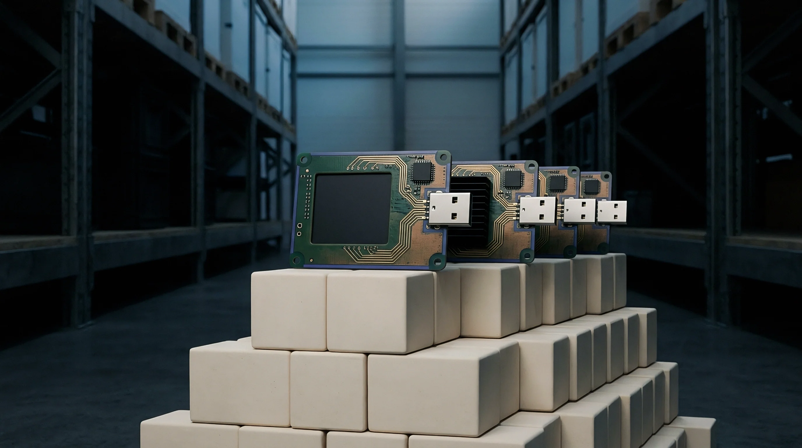
Unit cost represents only part of the true expense when integrating industrial wireless modules. Total landed cost includes unit pricing, import duties, software integration, certification maintenance, and long-term support. Commercial Wi-Fi modules typically run between 4 and 8 US Dollars in volume, but lack wide temperature ratings, extended availability, and heavy shielding.
Industrial modules cost between 15 and 35 US Dollars, a price premium that is generally offset by avoiding field service calls, emergency board spins, and line stoppages.
Relying on a single module supplier leaves production vulnerable to component shortages, sudden End-Of-Life notices, and trade disruptions. Securing a pin-compatible second source during initial board design protects production lines. Designing dual-footprint PCB layouts allows either vendor module to be mounted without requiring a board revision, while standardized software abstraction layers ensure the host application runs identically regardless of which radio chip is populated.
The table below breaks down the comparative cost factors governing module selection, re-certification risks, and long-term maintenance commitments.
| Cost Component Category | Commercial-Grade Module Path | Industrial-Grade Module Path | Financial Variance Analysis |
|---|---|---|---|
| Initial Unit Price (10k units) | $5.80 per unit | $22.50 per unit | Industrial path adds $167,000 unit cost |
| System Modular Re-Certification | $12,000 (frequent spins) | $3,500 (stable design) | Commercial path incurs $8,500 extra testing |
| Field Maintenance Overhead (5 years) | $85,000 (high failure rate) | $14,000 (extended temp spec) | Industrial path saves $71,000 service expense |
| Total Landed Five-Year Spend | $155,000 total outlay | $242,500 total outlay | Industrial premium yields 99.99 percent uptime |

Total Cost of Ownership and Lifecycle Operations
Calculating total cost of ownership involves looking at the effective cost per delivered packet over time. In a facility transmitting telemetry every 100 milliseconds, dropped frames trigger retransmissions that consume spectrum and extend host CPU wake cycles. A cheap module with a 15 percent frame loss rate increases overall power draw and lowers capacity, often requiring additional access points to plug coverage gaps.
Investing in modules with better receiver selectivity and low EVM reduces necessary access point density, lowering broader plant infrastructure costs.
Ongoing firmware maintenance forms a significant portion of operational expenditure. Software support varies widely across component vendors; established suppliers provide security patches, WPA3 updates, and driver fixes for ten years or more after launch. Choosing budget modules with limited vendor support forces internal engineering teams to maintain custom driver forks, diverting engineering resources away from core product features.
Managing component obsolescence requires contractual safeguards. Industrial product lifecycles typically run ten to fifteen years, while consumer chipsets refresh every two to three years. Supplier contracts should include formal End-Of-Life terms that guarantee at least a two-year last-time-buy window and rights to full manufacturing design packages if the vendor discontinues production.