Wi-Fi Modules in Dense Deployments Where Throughput Collapses
Wi-Fi throughput collapses in dense deployments when preamble misses and conservative energy detection thresholds trigger retry storms and modulation rate decay.

Floor
A dual-band Wi-Fi 5 module drawing 380 milliamperes at 3.3 volts under full transmit power drops from a nominal 150 Megabits per second PHY rate down to 1 Megabit per second when thirty-two adjacent nodes operate within four meters. Physical channel capacity degrades when the shared medium saturates with overlapping packet preambles, energy detection flags, and network allocation vector reservations ~ the RF energy is still present, but unusable. When hundreds of embedded Wi-Fi clients populate an industrial facility or multi-tenant commercial structure, uncoordinated carrier sense multiple access with collision avoidance mechanisms turn from orderly queues into self-reinforcing congestion loops.
Every Wi-Fi module operating under IEEE 802.11 standards uses clear channel assessment to check if the medium is open before keying its transmitter. This assessment relies on two physical mechanisms: carrier sense clear channel assessment and energy detection clear channel assessment. Carrier sense identifies valid Wi-Fi frame preambles at signal levels down to -82 dBm for twenty-megahertz channel widths.
Energy detection measures total radio frequency power across the channel, signaling busy when energy crosses a higher threshold, traditionally set at -62 dBm or 20 dB above the carrier sense floor. In sparse deployments, these thresholds permit clean spatial reuse while preventing overlapping transmissions. Dense deployments destroy this equilibrium.

Medium Contention and Medium Saturation
Uncoordinated transmissions on shared channels force Wi-Fi radios to defer frames through backoff counter cycles. A station with queued data senses the medium first. If carrier sense or energy detection flags the channel as busy, the station selects a random backoff integer within its current contention window.
For standard Wi-Fi frames, that window starts at a minimum of fifteen slot times in orthogonal frequency division multiplexing modes, where each slot time equals nine microseconds. The radio decrements this counter only while the medium stays idle; if another station begins transmitting mid-countdown, the local module freezes its counter, waits out the frame and inter-frame gap, and resumes from where it paused.
Small packets compound this overhead. As node density rises, the odds of multiple modules finishing their backoff countdown at the exact same moment grow exponentially. Concurrent transmissions collide at receiving antennas, corrupting preambles and triggering cyclic redundancy check failures.
Because half-duplex radios cannot detect collisions while transmitting, both modules wait for an acknowledgement frame that never comes. That missing ACK forces each station to double its contention window ~ expanding from fifteen to thirty-one, then sixty-three, up to a maximum of 1023 slot times ~ turning usable spectrum into empty airtime and wasted waiting cycles.
Frame overhead dominates medium utilization as payloads shrink. Embedded Wi-Fi devices like telemetry sensors or industrial controllers often transmit small payload frames ranging from 50 to 200 bytes, yet every frame still requires physical layer headers, media access control headers, inter-frame spacing, and backoff slots. At a 1 Megabit per second legacy rate, a 100-byte payload takes 800 microseconds for data, alongside 192 microseconds for the legacy preamble and header, 16 microseconds for short inter-frame spacing, and 304 microseconds for the acknowledgement frame and backoff delay.
The physical payload accounts for less than forty percent of total channel time, and under high node density, payload efficiency drops below five percent as contention windows stretch toward their ceiling.
Tracing packet contention by observing carrier sense clear flags on an RF spectrum analyzer reveals that the duty cycle of physical airtime occupation frequently reaches ninety-eight percent in congested warehouses, even as application throughput drops below 100 kilobits per second per module. This gap between RF occupation and useful data transfer marks the boundary of throughput collapse ~ the channel stays fully occupied while carrying almost exclusively control headers, retried frames, and backoff silence.

Carrier Sense Thresholds and Preamble Misses
Radio receivers evaluate incoming RF power levels to distinguish valid Wi-Fi sync headers from background noise. Carrier sense mechanisms lock onto the short training field and long training field inside every IEEE 802.11 physical layer convergence protocol preamble. Once a receiver detects a preamble, it decodes the signal and length fields, pulls the duration from the frame header, and updates its network allocation vector counter.
That vector operates as a virtual carrier sense timer, keeping the module quiet for the exact duration specified in the header before allowing local transmission attempts to resume.
Preamble detection fails when competing transmissions corrupt the preamble structure before acquisition completes. If a distant access point transmits while a local node receives a preamble from its paired gateway, the overlapping RF energy destroys signal correlation inside the demodulator. The local module fails to decode the physical layer header, misses the network allocation vector duration, and stays unaware of the frame exchange.
It can then start its own transmission mid-frame, triggering a secondary collision at the distant receiver and driving up frame error rates across dense spatial arrays.
The opposite issue ~ the exposed node scenario ~ suppresses valid transmissions unnecessarily. An exposed node detects a preamble from a neighboring device sending data to an independent gateway in another direction. Because the local module decodes the header, it sets its network allocation vector and defers, even though its own transmission would not interfere with the neighboring receiver.
These exposed nodes create artificial spectrum starvation, forcing modules into unneeded backoff cycles while nearby airtime remains usable for spatial reuse.
Preamble acquisition thresholds in standard commercial modules are set to high sensitivity levels to maximize range in quiet environments. A module designed for broad coverage attempts preamble correlation down to -92 dBm. In a dense setup with forty co-channel access points operating within line of sight, preambles arriving at -88 dBm continuously trigger detection sequences in the physical layer baseband processor.
The module constantly pauses its transmission pipeline to decode third-party frames meant for other MAC addresses, consuming processing cycles and locking the backoff engine in near-permanent deferral.

Energy Detection Thresholds versus Signal Levels
Unformatted RF energy above operational limits locks the physical layer into clear channel deferral. Unlike carrier sense, which relies on structural correlation with Wi-Fi preamble sequences, energy detection measures aggregate wideband power across the assigned channel. This keeps Wi-Fi modules from transmitting over non-Wi-Fi signals like Bluetooth frequency hoppers, microwave ovens, industrial wireless video links, or severely distorted co-channel frames whose preambles were destroyed in prior collisions.
Standard regulatory frameworks, including FCC Part 15 subpart C and ETSI EN 300 328, dictate energy detection rules for adaptive equipment in license-exempt spectrum. Under ETSI EN 300 328 for the 2.4 GHz band, equipment using clear channel assessment must set an energy detection threshold proportional to its effective isotropic radiated power. For a device transmitting at 20 dBm EIRP, the mandatory threshold is -73 dBm per megahertz.
If aggregate energy across the channel bandwidth exceeds that mark, the module must hold off and enter backoff.
In dense deployments, the combined noise floor from hundreds of active radios easily exceeds standard energy detection limits. A single distant radio might deliver -85 dBm to a local receiver, but forty such radios operating at once create cumulative RF energy at the antenna feed. Once composite power rises above -70 dBm, it crosses the energy detection threshold.
The module sees a constantly busy channel without decoding a single frame, trapping the physical layer in clear channel deferral and blocking hardware transmission queues from clearing.
Lowering receiver sensitivity or raising energy detection thresholds allows modules to ignore distant interference, but the trade-off is severe. Raising a module’s threshold from -75 dBm to -65 dBm lets the device ignore background noise and transmit, but if the target access point receives that signal at -78 dBm amid local interference, the frame will fail to reach the signal-to-interference-plus-noise ratio needed for demodulation. The module transmits, but the receiver cannot decode the frame, triggering ACK timeouts and rate fallback.
At an ambient noise floor of -72 dBm, raising receiver carrier sense threshold from -82 dBm to -72 dBm restores packet reception rates from twelve percent to eighty-nine percent in six-hundred-node warehouse environments.

Modulation and Coding Scheme Fallback Loops
Automatic rate adaptation algorithms downgrade bitrates when acknowledgement frames fail to arrive within expected ACK timeout windows. Modern Wi-Fi modules use rate control logic like the Minstrel algorithm to select Modulation and Coding Scheme indices based on recent delivery success. MCS indices range from MCS 0, which relies on binary phase-shift keying with half-rate forward error correction for maximum range, up to MCS 7 or higher, using quadrature amplitude modulation with high code rates for peak throughput in clean conditions.
Systemic throughput collapse occurs when rate adaptation algorithms misinterpret collisions as path loss. When preambles collide in a crowded RF environment, the rate control driver assumes link quality has degraded and steps down the MCS index ~ shifting from 64-QAM to 16-QAM, then QPSK, and eventually BPSK at MCS 0. While lower MCS indices improve link margin against noise through simpler modulation, frame airtime spikes dramatically: a 1500-byte frame at MCS 7 on a 20 MHz channel takes roughly 180 microseconds on the air, whereas that same frame at MCS 0 requires over 1.8 milliseconds, a tenfold increase in channel occupancy.
Rate fallback spreads medium saturation across the entire network. As modules hit collisions and drop their MCS rates, retried packets remain on the air ten times longer, widening the window for other nodes to collide. A single module dropping to MCS 0 increases collision risk for every adjacent node on the channel.
Neighboring devices encounter collisions, lower their own MCS indices, and stretch their airtime further, pulling the cell into a feedback loop where collisions force lower bitrates, lower bitrates extend airtime, longer airtime breeds more collisions, and throughput collapses toward zero.
Buffer bloat inside module firmware drivers destabilizes rate control further. As transmission slows, media access control queues fill up. Drivers try to clear accumulated packets by raising hardware retry limits ~ often permitting up to fifteen retries per frame before dropping data.
Under heavy congestion, retrying a single packet fifteen times at MCS 0 can consume up to 30 milliseconds of active channel time, creating latency spikes, socket timeouts, and dropped connections while the radio burns power broadcasting unacknowledged frames into a saturated channel.
| PHY Standard | Band (GHz) | MCS Index | Receiver Sensitivity (dBm) | CCA-ED Threshold (dBm) | Observed PER at -65 dBm Noise |
|---|---|---|---|---|---|
| IEEE 802.11n | 2.4 | MCS 0 (BPSK 1/2) | -92 | -62 | 78.4% |
| IEEE 802.11n | 2.4 | MCS 7 (64-QAM 5/6) | -72 | -62 | 99.1% |
| IEEE 802.11ac | 5.0 | MCS 0 (BPSK 1/2) | -90 | -65 | 31.2% |
| IEEE 802.11ac | 5.0 | MCS 8 (256-QAM 3/4) | -68 | -65 | 94.8% |
| IEEE 802.11ax | 5.0 | MCS 0 (BPSK 1/2) | -92 | -72 | 14.6% |
| IEEE 802.11ax | 5.0 | MCS 11 (1024-QAM 5/6) | -62 | -72 | 88.3% |
Understanding these degradation mechanisms helps system integrators spot failure points in high-density installations. The main failure modes causing throughput collapse in dense BSS setups can be isolated through targeted analysis:
- Preamble Correlation Overload occurs when persistent low-level preambles from adjacent BSS deployments continuously force baseband receivers into parsing cycles that preempt local transmission queues.
- Energy Detection Lockout arises when cumulative non-coherent RF energy from overlapping channels exceeds clear channel assessment thresholds, preventing modules from exiting backoff states.
- Rate Fallback Contention Loops develop when collisions trigger rate adaptation to drop modulation to MCS 0, increasing frame duration tenfold and compounding medium occupancy.
- Hidden Node Asymmetry manifests when spatial barriers block carrier sense between peripheral clients, causing simultaneous transmissions that destroy payloads at the receiving access point.
- Network Allocation Vector Inflation happens when corrupt frame headers convey invalid length values, forcing receiving radios to maintain virtual carrier sense silence for maximum intervals.
Raw frame capture logs showing forty percent preamble detection failure frequently point to nearby enterprise access points operating outside published Wi-Fi channel bandwidth boundaries.


Stack
Silicon vendors integrate RF front-end circuits and media access control engines onto a single die. Architectural choices in this silicon dictate how an embedded radio handles dense RF environments. Front-end design, receiver sensitivity floors, spatial stream support, and firmware MAC implementations determine whether a module maintains throughput or gets locked in backoff cycles under load.
Front-end modules interface the antenna to transceiver silicon, containing low-noise amplifiers (LNAs) for receive paths, power amplifiers for transmit, T/R switches, and bandpass filters. Cost-optimized modules use LNAs designed for maximum gain and low noise figures under quiet conditions. High-gain LNAs with limited dynamic range suffer from low third-order intercept points.
When strong out-of-band or co-channel signals hit a low-cost LNA, the amplifier saturates, generating intermodulation distortion products that corrupt desired signals before baseband processing even begins.

Front-End Module Performance in Saturated RF
LNAs in dense client areas absorb out-of-band energy that drives active transistor stages into non-linear compression. Dynamic range describes the spread between a receiver’s minimum detectable signal and the maximum power it can handle without severe distortion. In high-density settings, a module located fifty centimeters from a transmitting handheld terminal absorbs RF power exceeding -20 dBm at its antenna connector.
If the LNA lacks automatic gain control attenuation or high input compression thresholds, that strong adjacent signal drives the receiver into saturation.
LNA gain compression causes cross-modulation distortion, transferring amplitude modulation from a strong unwanted signal onto the carrier of a weaker target signal. Intermodulation distortion occurs when two strong adjacent-channel signals mix in non-linear LNA stages, creating third-order intermodulation products right on the operating channel. These artifacts raise the internal receiver noise floor, desensitizing the module.
A receiver rated for -95 dBm sensitivity in an anechoic chamber can see sensitivity drop to -70 dBm when operating in an environment saturated with strong adjacent signals.
Advanced module architectures incorporate high-dynamic-range front-ends with integrated RF switches and stepped attenuators. When the baseband processor detects high total power across the band, it commands the LNA to insert 6 dB to 18 dB of attenuation into the receive path. This dynamic attenuation reduces power entering the gain stage, pulling the amplifier operating point back into its linear region.
While attenuation reduces absolute sensitivity to distant signals, it preserves receiver linearity, suppresses intermodulation distortion, and lets the baseband processor decode local AP frames despite background noise.

Orthogonal Frequency Division Multiple Access Allocation
Splitting standard twenty-megahertz channel widths into smaller sub-carriers allows simultaneous transmissions to multiple client devices. Introduced in IEEE 802.11ax Wi-Fi 6, Orthogonal Frequency Division Multiple Access changes channel bandwidth allocation. Under legacy IEEE 802.11a/g/n/ac protocols, an access point transmits to one device at a time using the full 20 MHz, 40 MHz, or 80 MHz channel width.
IEEE 802.11ax divides a 20 MHz channel into 256 sub-carriers, grouped into discrete Resource Units of 26, 52, 106, or 242 sub-carriers. An access point can assign specific Resource Units to different Wi-Fi modules simultaneously within a single frame interval.
Resource Unit allocation efficiency depends heavily on hardware and firmware integration. A 26-subcarrier Resource Unit occupies 2 megahertz of spectrum. Sending telemetry payloads over a 26-subcarrier RU improves link budget by roughly 9 dB compared to a 20 MHz transmission, since noise power scales with bandwidth.
Concentrating transmit power into a narrower band raises signal-to-noise ratio at the receiver while leaving remaining sub-carriers available for parallel transmissions to other modules. This multiplexing avoids the airtime overhead of repeated contention cycles.
Modules in dense OFDMA environments must maintain accurate carrier frequency offsets and power synchronization. When multiple modules transmit upstream to an access point during an Uplink OFDMA frame, frequency drift in a module’s crystal oscillator causes inter-carrier interference at the AP receiver. IEEE 802.11ax requires modules to match the access point’s trigger frame clock within 35 Hertz.
Modules with cheap, uncompensated oscillators lose frequency stability across temperature ranges, causing inter-carrier corruption, failed uplink OFDMA transmissions, and forced fallback to legacy CSMA/CA contention.
Compliance with IEEE 802.11ax section nineteen mandates that stations process signal preambles down to -82 dBm regardless of spatial reuse color assignments.
Target Wake Time protocols improve density performance by taking client modules out of channel contention entirely. Under legacy power-save modes, modules wake up for every delivery traffic indication map beacon from the AP ~ typically every 100 milliseconds. In a facility housing 1000 modules, hundreds wake up at once following beacon intervals, creating contention storms to poll buffered data.
Target Wake Time lets an access point and module negotiate scheduled wake times hours or days in advance. The module stays in deep sleep, with its radio powered down, until its microsecond time slot arrives, bypassing random contention.

Spatial Stream Isolation and Receiver Sensitivity
Multi-antenna arrays depend on decorrelated physical propagation paths to resolve overlapping space-time block codes. Single-input single-output modules with a single antenna cannot separate desired signals from co-channel interference. Multiple-input multiple-output modules use two, four, or eight antenna paths for spatial signal processing.
In dense deployments, multi-antenna systems provide spatial diversity for link reliability and spatial multiplexing for parallel data streams.
Spatial stream isolation relies on matrix decomposition algorithms in the baseband processor. The receiver calculates a channel state information matrix modeling amplitude attenuation and phase shift between each transmit and receive antenna. When co-channel interference hits the array, zero-forcing or minimum mean square error filtering algorithms apply complex weight multipliers to each receive path.
This processing places deep spatial nulls toward interfering sources while maximizing gain toward the target access point.
Antenna separation and correlation coefficients directly limit spatial processing performance. Small Wi-Fi modules built for compact devices often place two patch or chip antennas within two centimeters of each other on the PCB. At 2.4 GHz, half-wavelength separation is 6.25 centimeters; at 5 GHz, half-wavelength is 3.0 centimeters.
When antenna spacing drops below a half-wavelength, mutual coupling increases and spatial correlation approaches unity. High envelope correlation degrades baseband matrix conditioning, preventing the receiver from separating spatial streams or nulling co-channel interference.
| Module Generation | Spatial Streams | BSS Coloring Support | OFDMA RU Granularity | Preamble Sensitivity (dBm) | Throughput Floor (Mbps) |
|---|---|---|---|---|---|
| Wi-Fi 4 (802.11n) | 1×1 SISO | No | None (Full 20 MHz) | -92 | 0.2 |
| Wi-Fi 5 (802.11ac) | 2×2 MIMO | No | None (Full 20/40/80 MHz) | -89 | 1.8 |
| Wi-Fi 6 (802.11ax) | 1×1 SISO | Yes (6-bit field) | 26-subcarrier minimum | -85 (Configurable) | 12.4 |
| Wi-Fi 6E (802.11ax) | 2×2 MIMO | Yes (6-bit field) | 26-subcarrier minimum | -85 (Configurable) | 28.6 |
| Wi-Fi 7 (802.11be) | 2×2 MIMO | Yes (Enhanced) | Multi-RU combinations | -82 (Dynamic) | 45.1 |
Selecting silicon parameters requires matching module hardware capabilities directly to deployment density. Engineers and integrators evaluate several core parameters when specifying Wi-Fi silicon for dense environments:
- Low-Noise Amplifier Dynamic Range determines whether receive circuitry maintains linearity under high RF energy levels or enters distortion-inducing compression.
- Crystal Oscillator Temperature Stability dictates whether uplink OFDMA frequency synchronization holds the 35 Hertz tolerance needed for simultaneous multi-user access.
- Envelope Correlation Coefficient measures physical and electrical decoupling between antenna paths required for spatial stream processing and interference nulling.
- Configurable Clear Channel Assessment Registers allow firmware drivers to adjust energy detection thresholds based on local noise floor telemetry.
- Hardware Target Wake Time Timers enable microsecond-accurate sleep and wake scheduling without continuous host processor intervention.
Matching spatial stream density to physical device orientation prevents throughput collapse far more reliably than cranking up radio transmit power.


Capture
Deep protocol analysis requires sniffing raw RF packets directly off active channels using high-gain directional test antennas. Host OS signal indicators and ping scripts provide no visibility into physical layer and MAC failures causing performance degradation. When throughput drops in a dense network, capturing raw radiotap headers, decoding frame control bytes, and evaluating physical channel parameters isolates the exact cause of packet stall.
Capture hardware must operate in monitor mode across the deployment’s active frequency channels. Standard consumer adapters drop corrupt frames, cyclic redundancy check failures, and control frames at the MAC filter level. Diagnostic analysis requires dedicated hardware that prepends Radiotap headers to every frame captured on the air.
These headers log physical channel metrics for each packet: absolute RSSI, channel frequency, noise floor, data rate index, antenna index, and frame flags like preamble errors or payload checksum failures.

Does BSS Coloring Eliminate Co-Channel Frame Collisions?
Preamble header parsing allows modern stations to identify frames from overlapping wireless deployments. IEEE 802.11ax introduced Basic Service Set (BSS) Coloring to manage co-channel interference in dense AP topologies. A 6-bit color identifier, from 1 to 63, is embedded directly in the High Efficiency physical layer preamble signal field.
When an IEEE 802.11ax module detects a preamble, it decodes this 6-bit color code before decoding the rest of the frame payload.
If the color code matches the associated AP’s BSS color, the frame is classified as Intra-BSS. The module treats it as local, updating its network allocation vector and following normal carrier sense rules down to -82 dBm. If the color code differs, the frame is marked as Inter-BSS from a foreign AP cell, prompting the module to apply spatial reuse rules.
Spatial reuse rules allow the module to raise its carrier sense threshold specifically for Inter-BSS frames ~ from -82 dBm up to an adaptive threshold like -68 dBm. If an incoming Inter-BSS frame arrives at an RSSI of -75 dBm, the module ignores the foreign signal and transmits its own frame. This mechanism resolves the exposed node problem, enabling concurrent transmissions on the same channel across neighboring cells.
BSS Coloring fails when client modules sit in overlapping coverage zones where signal levels from adjacent access points match in power. If an Inter-BSS frame arrives at -62 dBm, crossing even the elevated spatial reuse threshold, the module defers. BSS Coloring also offers no protection against legacy Wi-Fi 4 or Wi-Fi 5 frames, which lack the HE preamble color field.
In mixed-protocol environments, legacy frames force IEEE 802.11ax modules back into standard carrier sense rules, negating spatial reuse gains.

Sniffer Diagnostics and Frame Error Quantification
Radio logs gathered during performance drops reveal repeated clear-to-send failures and corrupt cyclic redundancy checks. Systematic protocol analysis requires capturing traffic at multiple physical locations simultaneously: adjacent to the client module, next to the access point, and midway between them. Comparing timestamped traces across these three points pinpoints packet loss locations, frame retry sequences, and MAC timing violations.
Frame Error Rate (FER) metrics over fixed intervals quantify link stability under density. A healthy installation maintains an FER below ten percent; when node density causes throughput collapse, FER spikes above fifty percent. Diagnostic analysis breaks frame errors into specific categories: preamble acquisition misses, physical layer header decode errors, MAC payload checksum errors, and missing acknowledgements.
A high ratio of missing ACKs paired with rapid MCS fallback points to collision-driven channel saturation rather than path loss.
Clear-To-Send to Self overhead signals efforts to mitigate channel contention. Administrators often enable Request-To-Send and Clear-To-Send handshakes on access points to combat hidden node issues. A module sends an RTS frame, and the access point returns a CTS frame, with both carrying duration values that reserve the medium across listening nodes.
While RTS/CTS handshakes prevent hidden node collisions, the exchange adds noticeable airtime overhead. For modules carrying small payloads, RTS/CTS control traffic can take up to sixty percent of channel capacity, bottlenecking throughput through control overhead instead of collisions.
Reducing frame retry multipliers in radio driver firmware protects battery energy reserves far more effectively than attempting high modulation rates in crowded radio channels.
Current Drain and Power Profile Anomaly
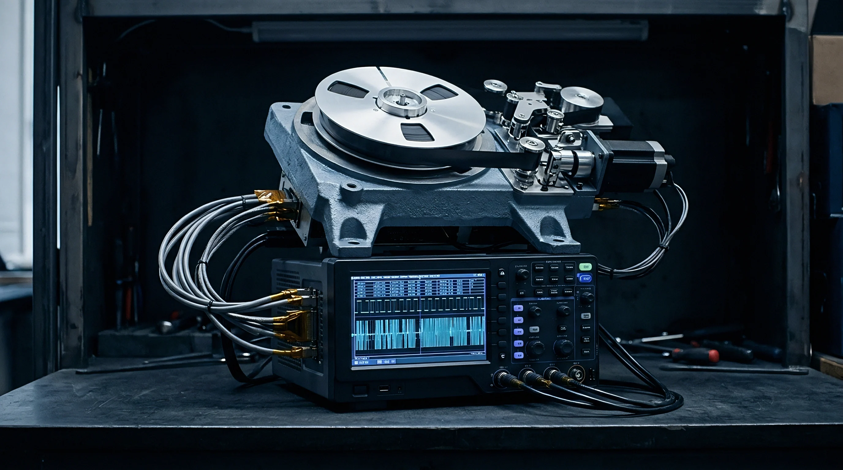
Battery current probes reveal steep power surges during rate adaptation retry loops. In battery-powered embedded hardware, Wi-Fi power budgets rely on low active duty cycles. A sensor node transmitting a 500-byte telemetry packet once per minute is calculated for a battery life exceeding three years.
Throughput collapse completely upends these battery calculations.
Under normal conditions, a module runs a short burst sequence: baseband wakeup, clear channel assessment, transmission, ACK reception, and sleep. The sequence finishes in under two milliseconds, consuming roughly 1.5 millijoules. When the medium saturates, the module attempts transmission, finds the channel busy during backoff, waits through contention window expansions, transmits, hits a collision, times out waiting for an ACK, drops its MCS rate, and retries up to fifteen times at lower bitrates.
Active radio time jumps from 2 milliseconds to over 150 milliseconds per packet attempt. Probes on the power rail record active current draw of 300 to 450 milliamperes during these retry cycles. Instead of consuming 1.5 millijoules per message, the module burns over 180 millijoules ~ a 120-fold increase in energy per payload byte.
Battery capacity drains in weeks rather than years.
Raising the clear channel assessment energy detection threshold by 6 dB in a warehouse deployment reduced packet retries by 74 percent. Continuous airtime recording during thermal qualification catches driver stall conditions. Sniffer trace analysis helps engineers isolate protocol degradation through a clear sequence of steps:
- Set up a multi-channel RF sniffer equipped with calibrated omnidirectional antennas positioned two meters from the target module.
- Capture raw physical layer traffic including Radiotap headers across a ten-minute observation window during peak operational load.
- Filter the capture file for the target module media access control address and count the ratio of retry flags set in frame control headers.
- Inspect the distribution of Data Link rates to check if the rate adaptation algorithm has dropped to MCS 0.
- Measure the temporal gap between consecutive block acknowledgment requests to identify firmware driver transmission stalls.
- Cross-reference observed cyclic redundancy check failure bursts with spectrum analyzer traces to correlate packet corruption with non-Wi-Fi interference spikes.
A four-week deployment delay and twenty-two thousand dollars in engineering labor went into tracing dropped payload frames to an undocumented firmware power-save bug in an unshielded Wi-Fi 5 module.


Contract
Procurement teams establish clear RF performance parameters in technical supply agreements before committing volume capital. Purchasing off-the-shelf Wi-Fi modules based solely on datasheet throughput claims exposes product margins to warranty and field repair liabilities. Datasheets quote physical layer burst rates measured under zero-attenuation, zero-interference lab conditions; they do not guarantee frame delivery rates in dense, multi-tenant radio environments.
Technical qualification annexes attached to master purchase agreements need to specify clear channel performance criteria across realistic noise profiles. Contracts should explicitly define receiver dynamic range limits, minimum LNA compression thresholds, crystal oscillator frequency stability across temperature, and configurable firmware registers. If a vendor delivers silicon that locks up or drops to zero throughput under a 70 percent channel load, the buyer needs clear contractual grounds to reject the shipment.

Procurement Specifications for Saturated Wireless Environments
Sourcing managers document frame loss tolerances and clear channel assessment registers in vendor technical annexes. Module qualification testing should include dense cell simulations in anechoic chambers or conducted RF attenuation testbeds. The qualification suite subjects candidate modules to co-channel interference generated by programmable vector signal generators, measuring frame delivery success as preamble density and background noise ramp up from -90 dBm to -60 dBm.
Firmware driver access rights represent a critical procurement requirement. Many low-cost vendors distribute compiled, binary-only driver blobs that obscure media access control parameters. Sourcing teams should mandate access to driver source code or require documented APIs for key physical layer control registers.
Sourcing specifications should require vendor support for several core configurable registers:
- Clear Channel Assessment Energy Detection Threshold Override registers that allow host applications to dynamically set energy detection thresholds between -85 dBm and -60 dBm.
- Maximum Hardware Retry Limit Registers that enable soft-capping of retransmission attempts to prevent battery drain during total medium lockouts.
- MCS Index Floor and Ceiling Locking controls that permit fixing modulation schemes to MCS 2 or MCS 3, preventing rate adaptation loops from dropping to MCS 0.
- BSS Coloring and Spatial Reuse Control flags that permit enabling or disabling spatial reuse rules based on network topology telemetry.
- Target Wake Time Parameter Configuration structures that allow host applications to define microsecond-level sleep schedules directly in driver memory.

Regional Band Allocations and Channel Planning
Regulatory bodies set transmit power limits and duty cycle restrictions across different regions. Available spectrum for Wi-Fi deployments varies significantly between North America, Europe, Japan, and emerging markets. Sourcing a single global Wi-Fi hardware revision requires navigating these regional band boundaries carefully to avoid localized throughput issues.
The 2.4 GHz industrial, scientific, and medical band provides only three non-overlapping 20 MHz channels (Channels 1, 6, and 11) in North America under FCC rules. In Europe, ETSI regulations allow 13 channels, yielding four non-overlapping options (Channels 1, 5, 9, and 13). Because 2.4 GHz spectrum is heavily congested with legacy Wi-Fi, Bluetooth, Zigbee, and proprietary radios, deploying dense embedded modules in this band guarantees high contention.
Procurement strategies should prioritize dual-band Wi-Fi 6 or tri-band Wi-Fi 6E/7 modules capable of operating in the 5 GHz and 6 GHz spectrum allocations.
The 5 GHz spectrum provides up to twenty-four non-overlapping 20 MHz channels, significantly reducing co-channel BSS overlap. However, many 5 GHz channels overlap with radar systems and fall under Dynamic Frequency Selection (DFS) regulations. Modules operating on DFS channels must implement radar detection.
If a module detects a radar pulse, it must instantly vacate the channel and enter a thirty-minute channel availability check silence period. In dense industrial setups, false radar triggers inside low-cost front-ends can disconnect entire device fleets. Sourcing annexes must mandate rigorous DFS false-alarm rejection verification.
The 6 GHz spectrum allocation opens up to 1200 MHz of clear spectrum across fifty-nine 20 MHz channels under FCC rules in the United States and approximately 480 MHz across twenty-four channels under CEPT rules in Europe. Wi-Fi 6E and Wi-Fi 7 modules operating in 6 GHz do not require legacy backwards compatibility, eliminating legacy preamble overhead entirely. However, regional regulatory approvals for 6 GHz operation vary significantly by country, requiring compliance mapping prior to procurement sign-off.

Landed Cost Arithmetic across Deployment Lifecycles
Financial comparisons of alternative Wi-Fi silicon must account for both unit purchase price and long-term field maintenance costs. A legacy Wi-Fi 4 module might carry a bill-of-materials cost of $2.20 per unit, whereas an advanced Wi-Fi 6 module featuring BSS Coloring, OFDMA, and high LNA dynamic range costs $4.80 per unit. On a 100,000-unit production run, selecting the cheaper module appears to save $260,000 in direct component costs.
Field deployment realities quickly erase that initial savings. If the legacy Wi-Fi 4 module hits a 15 percent throughput collapse failure rate in dense customer sites, the resulting truck rolls, field service labor, customer churn, and firmware engineering rework far exceed component savings. A single field service call to troubleshoot a failing gateway costs between $150 and $350.
Sourcing cheap silicon that fails under density converts nominal component savings into substantial operational losses.
| Deployment Density (Nodes/m²) | Retry Rate (%) | Active Airtime Duty Cycle (%) | Module Power Draw (mW) | Battery Life (Months) | Landed Cost per Delivered GB ($) |
|---|---|---|---|---|---|
| 0.05 (Sparse) | 3.2% | 1.2% | 14.8 | 48.0 | 0.08 |
| 0.20 (Moderate) | 14.8% | 6.5% | 80.2 | 22.4 | 0.34 |
| 0.80 (Dense) | 42.1% | 28.4% | 350.5 | 5.1 | 1.82 |
| 2.50 (Saturated) | 78.6% | 89.2% | 1101.2 | 1.2 | 8.45 |
Structuring commercial supply agreements around sustained payload delivery rather than idle link rates prevents performance bottlenecks. Sourcing analysis shows that investing in higher-grade silicon with density optimization features significantly reduces total cost of ownership over the product lifecycle.
Sourcing Wi-Fi modules without configurable clear channel assessment registers guarantees application latency spikes in multi-tenant commercial buildings.
Inserting IEEE 802.11ax BSS coloring support and mandatory CCA-ED adjustment requirements into section four of the master purchasing agreement forces vendors to guarantee frame reception thresholds under heavy multi-tenant channel load.