Managing Host Integration Limits for Modular Radio Frequency Safety Certification
Modular radio safety grants void when host enclosures reduce antenna separation below 20 cm, forcing mandatory SAR testing and permissive change filings.


Coupling
Modular grants lock in output power, modulation settings, and minimum separation distances. Dropping that certified module into a compact host shifts the reactive near-field energy. Metal chassis walls, nearby ground planes, and battery enclosures distort radiation patterns, focusing localized electric and magnetic fields toward the product’s outer surface.
As a result, the RF safety test run on an open evaluation board no longer reflects exposure for the packaged device.
Distance dictates whether compliance requires Specific Absorption Rate testing or Maximum Permissible Exposure calculations. Transmitters used within 20 centimeters of the body trigger SAR testing in most major jurisdictions. Moving a module from an external dongle into an embedded handheld housing cuts the space between the radiating element and the user’s skin.
That tighter clearance dramatically increases energy absorption in surrounding tissue ~ cutting internal clearance by just five millimeters can triple peak 1-gram SAR values.

Spatial Separation and Radiated near Field Boundaries
Certification grants lay out clear minimum distance requirements. If a wearable or handheld housing places the internal antenna closer than the distance specified on the modular grant, the host requires re-evaluation. Antenna geometry shapes the reactive near-field boundaries ~ loop, patch, and inverted-F antennas concentrate dense electric or magnetic fields close to the element, while the host board’s ground plane dimensions alter both resonant frequency and peak absorption areas.
Conductive components near the active antenna act as parasitic radiators. Flex cables, camera modules, and shield cans pull in near-field currents and redistribute electromagnetic fields across the housing, producing unexpected hot spots far from the module itself. Compliance teams generally check clearance between conductive paths and the antenna perimeter before locking in the mechanical design.
Thermal Dissipation and Ground Plane Coupling Effects
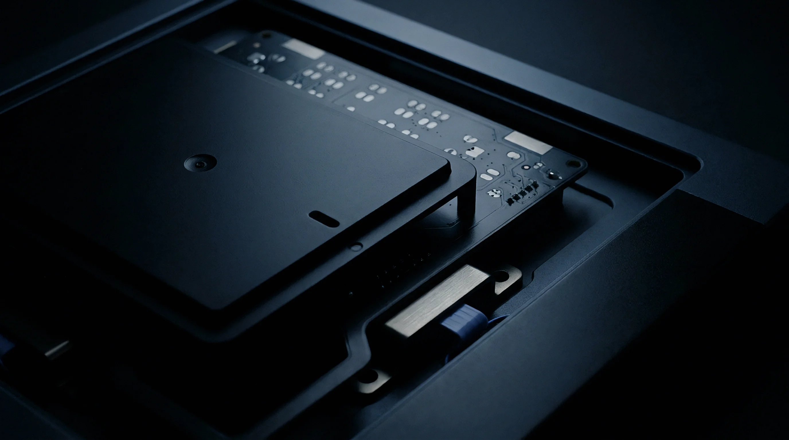
RF safety standards place hard caps on heat energy deposited in tissue. Dielectric losses in skin, muscle, and fat convert radiated waves directly into localized heat. When high-power radio modules transmit continuously inside tight plastic or metal housings, conductive dissipation through the chassis adds to the RF exposure, pushing up surface contact temperatures.
| Regulatory Jurisdiction | Governing Standard | Evaluation Metric | Head and Trunk Limit | Extremity Limit | Separation Distance Threshold |
|---|---|---|---|---|---|
| United States (FCC) | 47 CFR Section 2.1093 | 1-g SAR / 10-g SAR | 1.6 W/kg (1-g avg) | 4.0 W/kg (10-g avg) | 20 cm boundary |
| European Union (CE) | EN 50566 / EN 62209-2 | 10-g SAR | 2.0 W/kg (10-g avg) | 4.0 W/kg (10-g avg) | 20 cm boundary |
| Canada (ISED) | RSS-102 Issue 6 | 1-g SAR / 10-g SAR | 1.6 W/kg (1-g avg) | 4.0 W/kg (10-g avg) | 20 cm boundary |
| Japan (MIC) | Radio Law Article 14-2 | 10-g SAR | 2.0 W/kg (10-g avg) | 4.0 W/kg (10-g avg) | 20 cm boundary |
Thermal management directly affects radio duty cycles. Automated thermal throttling steps down the transmitter duty factor as junction temperatures hit internal limits, a behavior test labs account for during safety filings. Any software controls managing burst length or power backoff must be locked into firmware, and integrators have to prove those settings cannot be overridden by end users.
Federal Communications Commission rules treat any transmitter operating within 20 centimeters of human tissue as a portable device subject to specific exposure testing.
A standalone modular grant covers the board only in free space, not necessarily inside a finished product. Placing that module into a dense host assembly alters the electromagnetic environment, which invalidates baseline SAR test reports and usually requires additional evaluation.


Probe
Testing labs rely on liquid phantoms and robotic arms to map exposure profiles. Specific liquid mixtures match the permittivity and conductivity of human tissue across target frequency bands. Robotic arms lower electric field sensors into the fluid, taking measurements along three axes, which the system then maps into spatial absorption distributions across a defined grid.
Engineers mount the complete host against flat or head-shaped phantom shells. Small details like cable routing, battery charge levels, and mounting clips affect repeatability. Running the radio at full output power across low, mid, and high channels isolates worst-case exposure, while a turntable rotates the unit to locate peak emission vectors relative to the phantom.

Dosimetric Liquid Calibrations and Specific Absorption Rate Testing
Tissue-simulating liquids lose accuracy over time through evaporation and temperature shifts. Test operators verify permittivity and conductivity before each test run using a coaxial dielectric probe. Keeping lab temperatures within a tight ±2 °C window helps preserve fluid properties, since shifts in dielectric constants distort field distributions and throw off calculated absorption values.
First, broad area scans map emissions across the full face of the enclosure. When the system identifies peak coordinates, the robot switches to a dense zoom scan focused on the highest reading. Grid spacing drops to five millimeters or tighter above three gigahertz.
Algorithms then interpolate field data across the 3D voxel grid to calculate peak spatial-average mass absorption.

Power Density Measurements in Millimeter Wave Hosts
Above six gigahertz, regulatory evaluation shifts from mass absorption to absorbed power density, as millimeter-wave signals only penetrate superficial dermal layers. Standard liquid phantoms are replaced by free-space field mappers with optical or miniature wave sensors, measuring incident power density in watts per square meter across set averaging areas.
Calculations factor in actual duty cycles. A handheld scanner operating at a five percent burst cycle deposits far less thermal energy than a device streaming continuous video. Test plans use source-based time-averaging factors based on the host’s transmission protocol, but those duty cycles must match hardcoded software limits verified through lab trace captures.
For example, a 5.8 GHz industrial IoT module producing 200 milliwatts of raw conducted power easily complies on an open evaluation board at 20 millimeters, measuring a 1-gram SAR of 0.84 W/kg. Once installed in a ruggedized housing, an internal steel bracket reflects energy back toward the display face. Re-testing the assembled device at the same 20-millimeter distance yields a peak 1-gram SAR of 1.72 W/kg ~ exceeding the 1.6 W/kg limit.
Fixing this requires either hardcoding a 1.5 dB power reduction in firmware or altering the internal chassis layout to restore field symmetry.
Inaccurate probe placement or poorly calibrated dielectric fluid invalidates test data. Submitting flawed chamber reports to certification authorities risks audit flags, suspended grants, and holds on market inventory.


Permissibility
Regulatory frameworks set specific conditions for transferring modular approvals into finished devices. The grant conditions dictate whether an integration qualifies for simple registration or demands a formal permissive change filing. Reviewing grant notes early helps align host design with the original test setup, avoiding shipping delays or compliance breaches.
Altering antenna type, increasing gain, or reducing separation distance voids the modular authorization terms. Swapping an internal trace antenna for a higher-gain external whip increases effective isotropic radiated power, changing both spurious emissions and RF exposure. Integrators evaluate these shifts to choose the right filing class before starting mass production.

Specific Authorization Scope under FCC KDB Guidance
FCC guidance under KDB 996369 lays out manufacturer responsibilities. Full modular approval allows installation in fixed or mobile devices without new safety filings as long as antenna separation remains above 20 centimeters. Limited modular approval carries tighter constraints, such as dedicated power supply regulation or professional installation.
In all cases, the host integrator remains responsible for final compliance in the fully assembled product.
Class I permissive changes handle minor adjustments that do not alter RF performance or exposure figures. Class II changes require submitting fresh test data to a Telecommunication Certification Body. Reduced separation distance or added housing shielding trigger Class II procedures.
These filings remain tied to the original modular Grantee unless a formal Change in Identification is completed.

When Does Host Enclosure Alteration Force Class II Permissive Change Filing?
Changing housing materials directly impacts RF behavior. Replacing ABS plastic with carbon-fiber resin adds conductive attenuation and internal field reflections. If the module sits within 20 centimeters of human tissue, this modification invalidates baseline safety evaluations and requires chamber testing to establish revised absorption values.
| Integration Condition | Antenna Status | Separation Distance | Filing Classification | Required Test Scope |
|---|---|---|---|---|
| Same type, equal/lower gain | Unchanged | Greater than 20 cm | Host Verification | Unintentional radiator EMC pre-scan |
| Same type, higher gain | Modified | Greater than 20 cm | Class II Permissive Change | Radiated spurious and power density |
| Portable placement | Unchanged | Less than 20 cm | Class II Permissive Change | Full SAR evaluation in host housing |
| New antenna geometry | Type Changed | Less than 20 cm | C2PC or New FCC ID | Full SAR and transmitter qualification |
Determining whether an integration requires a permissive change follows a standard review sequence.
- Review original modular Grant of Equipment Authorization notes for explicit restrictions regarding host separation distances, antenna types, and output power caps.
- Measure mechanical separation distance between all internal active antenna elements and the outer skin surfaces of the final host enclosure assembly.
- Compare proposed host antenna gain values across all operational frequency bands against maximum gain limits published in the original modular test report.
- Conduct pre-assessment chamber scans to verify host chassis structures do not concentrate radiated electric or magnetic near-field distributions.
- File Class II Permissive Change documentation with an accredited Telecommunication Certification Body prior to commercial shipment if host parameters exceed modular grant limits.
FCC KDB 996369 D04 mandates that host manufacturers perform spot-check radiated measurements to confirm secondary emissions remain compliant inside the final enclosure.
Under Section 2.933 of FCC rules, a host manufacturer can execute a Change in Identification to establish a new equipment authorization while citing existing module test data. Doing so transfers legal responsibility for ongoing radio safety compliance directly to the host manufacturer.

Simultaneity
Many compact host devices house multiple radios operating at the same time. A handheld terminal might pack Wi-Fi 6E, Bluetooth, and 5G cellular transceivers into one enclosure. Combined RF fields can push total exposure beyond individual transmitter limits, making cumulative exposure calculations necessary across all active links.
When internal antennas sit close together, regulatory bodies require combined exposure evaluations. If the calculated sum exceeds exposure limits, design teams must implement physical separation or firmware interlocks that restrict specific frequency combinations or scale back transmit power during joint bursts.

Aggregate Exposure Ratios for Multi Radio Systems
Simultaneous compliance is calculated using the Specific Absorption Rate Estimation Ratio or the Normalized Cumulative Exposure Ratio. Dividing each radio’s measured output by its regulatory limit gives an exposure fraction; summed across all active transmitters, this total must stay below 1.0. Reaching 1.05 forces a full multi-transmitter chamber evaluation.
Variable duty cycles complicate these calculations. A Wi-Fi radio transmitting in short bursts adds far less thermal energy than a cellular module running continuous frames. Host firmware often relies on time-averaged exposure algorithms to balance power budgets dynamically across active transceivers.

Antenna Placement Geometry and Volumetric Spatial Separation
Physical separation between antennas cuts near-field coupling and lowers combined exposure values. Placing Wi-Fi and Bluetooth antennas at opposite ends of the chassis isolates peak field regions and keeps localized absorption points from overlapping inside tissue.
Isolation between antennas needs to exceed 20 dB across shared bands to prevent cross-modulation. Non-linear interactions in front-end circuits generate intermodulation products that can trigger EMC failures. Mapping spatial absorption contours confirms that 1-gram peak volumes stay separate within the phantom.
Several common layout choices frequently trigger multi-radio safety failures during qualification testing.
- Antenna Proximity Clashes internal antennas placed within five centimeters of each other create overlapping absorption hot spots that push aggregate exposure ratios above unit thresholds.
- Conductive Path Bridging long copper traces or ungrounded display shield foils act as secondary parasitic radiators, transferring RF energy across host structural zones.
- Uncontrolled Multi-Band Bursts firmware configurations allowing simultaneous peak-power transmission on overlapping cellular and Wi-Fi bands break conservative exposure limits.
- Ground Plane Truncation cutting host ground planes to fit compact battery compartments alters antenna impedance matching, boosting localized near-field radiation levels.
Maintaining at least five centimeters between co-located antennas prevents localized absorption peaks from overlapping inside portable host enclosures.


Labelling
Regulations require clear proof that a finished product contains certified radio components. Missing, unreadable, or improperly formatted host labels invite customs delays and administrative recalls, which is why compliance teams inspect label artwork before signing off on production releases.
Tight enclosure surfaces on smaller devices make physical labels difficult to fit. Regulators allow e-labeling under set conditions, permitting certification marks and notices to sit within firmware system menus when an integrated screen is present.
Physical Enclosure Markings and User Manual Disclosures
External host labels must combine granted identification numbers with required regulatory text. FCC rules specify the phrase “Contains FCC ID:” followed by the module code, while EU directives require a visible CE mark, manufacturer details, and Radio Equipment Directive disclosures.
| Market Region | Physical Mark Requirement | Required Text Phrase | User Manual Mandatory Notice |
|---|---|---|---|
| United States | FCC ID (Host or Module) | Contains FCC ID: | RF Exposure compliance and separation distance warnings |
| European Union | CE Mark | Not applicable (Manufacturer ID required) | Simplified EU Declaration of Conformity and band power specs |
| Canada | IC / ISED Certification No. | Contains IC: | RSS-102 RF exposure compliance and antenna operating terms |
| Japan | Giteki Mark & R-Number | symbol with specific 10-digit code | Construction Type Certification compliance statement |
User manuals must include clear RF safety instructions. If compliance hinges on a five-millimeter separation distance, that limit must appear explicitly in the manual’s safety section. Leaving mandatory safety language out of localized manuals invalidates compliance filings in destination markets.

Electronic Screen Requirements for Integrated Host Assemblies
Electronic labeling must be accessible without special tools or access codes. Users must be able to reach compliance screens within three menu steps in the OS, with clear navigation instructions included in the user manual or packaging insert.
Regulatory graphics and text must sit in read-only memory so firmware updates or end users cannot alter them. Display screens must also offer enough resolution and contrast for customs inspectors to read compliance marks clearly.
Regulatory audits of integrated host products depend on a core set of engineering records.
- Modular Grant Copies official certificate documents issued by recognized Telecommunication Certification Bodies showing original module operating parameters.
- Host Integration Instructions detailed engineering manuals provided by the module vendor outlining mandatory antenna trace layouts and ground plane rules.
- Permissive Change Reports technical test data demonstrating host compliance under Class II Permissive Change procedures where applicable.
- Artwork Proof Documents mechanical drawings detailing physical label dimensions, material durability specifications, and exact placement coordinates on the host housing.
How do regulatory authorities verify electronic label accessibility when a host device experiences total battery drain during border customs audits?


Liability
Ignoring host integration requirements carries heavy commercial risk. Missing a Class II Permissive Change trigger can lead to market recalls, stop-sale orders, and administrative fines. If a non-compliant device hits retail shelves, the financial exposure lands on the host integrator, not the module supplier.
Chamber time in accredited facilities runs between $2,000 and $3,500 per day, making budget provisions for retesting essential. A failed SAR evaluation forces enclosure changes, firmware tweaks, and secondary lab cycles ~ slipping product schedules by six to twelve weeks if retests land in crowded lab queues.

Contractual Allocations for Retesting and Non-Compliance Fees
Supply agreements between integrators and vendors must clearly define compliance boundaries. Standard module warranties only cover performance on a generic evaluation board. Purchase agreements need explicit indemnification clauses if a vendor firmware update shifts RF exposure behavior on deployed units.
Sourcing teams structure contracts around firm compliance milestones, tying payments to complete modular documentation, test reports, and approved antenna lists. Missing files delay commercial launches, eroding margins on time-sensitive products.

Lead Time Schedule Impacts across Regional Market Gates
Approval workflows dictate release timelines across regional markets. While the European Union relies on self-declaration backed by technical construction files, jurisdictions in Asia require in-country sample testing through local accredited labs.
Accredited test laboratories charge full daily chamber rates regardless of whether a product passes or fails its initial radio safety pre-scan sweep.
For a simultaneous launch in North America and Europe, a host requiring a Class II Permissive Change in the U.S. faces a four-week TCB review. Concurrently, the EU Radio Equipment Directive route requires updated technical files reflecting EN 50566 test results. Executing parallel filings prevents an approval hold in one region from stalling global inventory distribution.
Skipping time or budget for host-level RF qualification leaves inventory stuck in customs warehouses. Reaching market smoothly takes disciplined mechanical integration, early pre-scan sweeps, thorough documentation, and ongoing compliance checks from initial layout through final release.