Modular Transceiver Host Integration under FCC Part 15 Rules
Host integrators preserve modular radio grants by honoring layout trace guidelines, verifying host spurious emissions, and displaying external FCC identifiers.

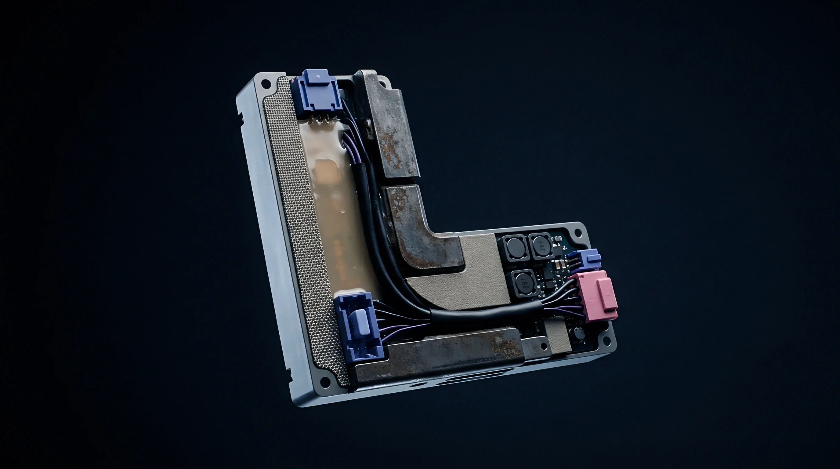
Shield
Integrated radio transmitters pass specific hardware design criteria to achieve standalone modular certification under Federal Communications Commission rules. Section 15.212 of Title 47 of the Code of Federal Regulations codifies eight physical and operational requirements governing whether an RF transmitter qualifies for full modular approval. A dedicated metallic radio frequency shield over the front-end circuitry serves as the primary physical boundary, isolating the modular oscillator and frequency-determining circuits from external host electromagnetic fields to prevent mutual coupling between digital buses and the radio front end.
If a module omits integral shielding, the Telecommunications Certification Body grants a Limited Modular Approval rather than a Full Modular Approval. This classification restricts installation to specific host enclosures tested and documented by the original grantee. Integrators evaluating datasheets look for independent regulatory filings rather than internal factory test reports; a full modular approval permits host integration across varied physical form factors without re-certifying the fundamental radio architecture, provided all grant conditions are strictly honored.
| Part 15.212 Rule Requirement | Hardware Implementation Mechanism | Integrator Compliance Obligation |
|---|---|---|
| RF Shielding (15.212(a)(1)(i)) | Solder-mounted metallic shield covering RF front-end | Verify shield remains intact without host modification |
| Buffered Data Inputs (15.212(a)(1)(ii)) | On-board integrated circuit bus buffers or transceivers | Prevent over-driving input lines beyond logic thresholds |
| Power Supply Regulation (15.212(a)(1)(iii)) | On-module low-dropout voltage regulator | Supply input voltage within specified module tolerances |
| Antenna Coupling (15.212(a)(1)(iv)) | Unique connector or permanently attached microstrip | Use only antenna types certified on the module grant |
| Standalone Testing (15.212(a)(1)(v)) | Module tested on extended test fixture outside host | Ensure host chassis does not supply radio shielding |
| Permanent Labeling (15.212(a)(1)(vi)) | Physical label or electronic screen ID display | Affix exterior host label containing module FCC ID |
| Specific Operating Rules (15.212(a)(1)(vii)) | Firmware locked to rule part power and frequency limits | Maintain default regulatory firmware configurations |
| RF Exposure Compliance (15.212(a)(1)(viii)) | Evaluated for minimum separation distance limits | Enforce installation distance and host co-location rules |
Buffered data and control inputs form the second major hardware barrier required by Part 15.212. Internal logic buffering ensures that excessive data rates or non-standard signal amplitudes from host microcontrollers cannot drive the modular transmitter into over-modulation or spurious spectral output. On-module power supply regulation performs a similar role for electrical noise, suppressing ripple originating from host switching converters.
If a transceiver relies on host-supplied voltage regulation, the regulatory filing falls back to a limited modular scope, binding the grant to specific power distribution architectures.
Radiated emission limits under Part 15.209 apply at a 3-meter measurement distance for frequencies above 30 MHz.
Host product engineering teams selecting transceivers review modular grant notes for explicit operational restrictions. A grant note citing limited modular approval shifts legal responsibility for RF boundary control back to the host assembler, who must coordinate with the module grantee to file a permissive change or execute joint compliance testing inside the final product enclosure before commercial distribution.
Module integration retains full compliance only when host power supply rails maintain noise floor integrity below the radio linear regulator rejection threshold.

Layout
Printed circuit board trace designs connecting a wireless transceiver to an internal antenna follow strict geometric parameters defined by the module grantee. When a modular transmitter lacks an integrated chip or patch antenna, the grantee files trace design instructions under Knowledge Database Publication 996369 D02 and D03. Microstrip lines, coplanar waveguides, and striplines must duplicate the physical stackup, dielectric constant, copper weight, and trace widths used during original certification.
Deviations in host circuit board materials alter the characteristic impedance of the antenna feedline, converting a matched 50-ohm transmission line into a reactive network. The resulting impedance mismatch increases return loss, forcing radio frequency energy back into the power amplifier and generating unwanted harmonic radiation. Host designers strictly maintain the board layer thickness, solder mask permittivity, and trace-to-ground spacing specified in the module integration manual to preserve compliance scope.
- Obtain trace routing schematics and Gerber file layers directly from the transceiver module manufacturer.
- Match host PCB dielectric constant and stackup thickness to the reference board evaluation parameters.
- Route RF microstrip lines with calculated 50-ohm characteristic impedance and continuous ground plane return paths.
- Execute time-domain reflectometry tests on initial host prototypes to confirm transmission line impedance within five percent.
- Perform radiated band-edge emission scans across fundamental radio frequencies inside a shielded enclosure.
Verifying host trace designs requires physical measurement prior to market entry. Integrators run time-domain reflectometry measurements on prototype boards to verify impedance tolerances along the entire path from transceiver pin to antenna pad. If a host design alters trace geometry, ground plane cutouts, or substrate suppliers, the host integrator can no longer claim coverage under the standard modular grant without secondary permissive change filings.
Minor adjustments to PCB laminate dielectric constants can still alter radiated harmonic emissions.

Proximity
Operational separation distance between an integrated transmitter antenna and the human body dictates the RF exposure evaluation path under Federal Communications Commission rules. Part 2.1091 defines mobile devices as equipment operating with a separation distance greater than 20 centimeters from nearby persons, while Part 2.1093 governs portable devices designed for use within 20 centimeters of the user’s body. Modular approvals granted under mobile conditions lose validity when integrated into handheld or wearable host form factors.
Portable host integration demands Specific Absorption Rate testing unless module output power falls below localized SAR exclusion thresholds outlined in KDB 447498. Calculating maximum permissible exposure involves assessing both peak radiated power and duty-cycle factors. When a host device houses multiple active transmitters, such as a cellular modem paired with Wi-Fi and Bluetooth modules, exposure calculations evaluate the simultaneous transmission total exposure ratio.
FCC Part 2.1093 dictates that modular transmitters approved for mobile separation distances cannot be placed within 20 centimeters of the human body without secondary SAR evaluation.
Simultaneous transmission analysis evaluates the cumulative radio frequency power density delivered to the user. The mathematical summation of normalized exposure ratios across all active transmitters must remain at or below 1.0. If the combined ratio exceeds unity, the host device requires physical SAR measurements inside an accredited laboratory using tissue-equivalent phantoms, regardless of individual modular grant certificates.
Host integrators must analyze antenna placement early in the mechanical design phase. Positioning an antenna adjacent to metallic battery casings, internal wiring harnesses, or metallic structural frames distorts the omnidirectional radiation pattern, creating localized spots of constructive interference that elevate local electric field strength and cause compliance failures during portable SAR scans.
How upcoming regulatory revisions to simultaneous transmission formulas will assess millimeter-wave beamforming transceivers in compact host bodies remains open.


Measurement
Physical evaluation of a fully assembled host device inside a calibrated semi-anechoic chamber verifies that digital noise and radio harmonics remain within legal limits. Integrating a pre-certified module does not grant total immunity from radiated emission testing. KDB 996369 D04 Host Product Testing Guidance outlines the engineering evaluation required for host products containing modular transmitters, requiring the host assembly to pass Part 15 Subpart B unintentional radiator testing to confirm high-speed digital clocks, power buses, and display drivers do not radiate beyond unlicensed equipment thresholds.

When Does Host Cabinet Radiated Emission Require Re-Filing?
Host cabinet radiation testing evaluates spurious emissions generated by interaction between the radio module and host electronics. The testing laboratory mounts the host product on a motorized turntable inside a semi-anechoic chamber, rotating the device 360 degrees while scanning up to 40 GHz with receive antennas positioned from one to four meters in height. Harmonic emissions from the transmitter can mix with host digital clock frequencies, producing intermodulation products that exceed Part 15.209 field strength limits.
| Compliance Scope | Applicable FCC Rule Part | Required Test Configuration | Documentation Output |
|---|---|---|---|
| Unintentional Radiator | Part 15 Subpart B (Class A or B) | Host active, radio in standby/receive mode | Supplier Declaration of Conformity or Test Report |
| Intentional Radiator Spot Check | Part 15 Subpart C / E | Host active, radio transmitting at max power | Verification lab report retained in technical dossier |
| Radiated Spurious Emissions | Part 15.205 / 15.209 | Host active, sweeping fundamental and harmonics | Engineering verification test report |
| Portable RF Exposure | Part 2.1093 / KDB 447498 | Host active, radio at max duty cycle near phantom | SAR Evaluation Report (or Exclusion Calculation) |
| Note: Measurements above 1 GHz utilize peak and average detectors per ANSI C63.10 procedures inside a 3-meter semi-anechoic chamber. | |||
Spot-checking protocols defined by industry practice involve taking radiated emission measurements at the fundamental operating frequency and across key harmonic channels. The laboratory verifies that host enclosure shielding does not distort the fundamental signal or trigger unwanted band-edge emissions. If spot checks reveal spurious outputs exceeding original modular grant values beyond normal measurement uncertainty tolerances, the host integrator must pause shipments and identify the coupling mechanism.
Host enclosures constructed of metallized plastic alter antenna radiation patterns and unpredictably shift peak harmonic frequencies during turntable rotation scans.
Engineers isolate radiation paths by selectively grounding internal cables, adding ferrite cores to interface lines, and retrofitting conductive gaskets along housing seams. Because radiated spurious emissions in restricted frequency bands listed under Part 15.205 enforce stricter field strength limits than non-restricted bands, failing to resolve restricted-band harmonic spikes prevents legal commercialization of the host assembly.
Integrating an RF module into a host without verifying Part 15 Subpart B digital compliance exposes the manufacturer to mandatory product market withdrawals and customs entry holds.


Amendment
Alterations to host hardware, antenna types, or mechanical enclosures require formal evaluation under Federal Communications Commission permissive change rules. Part 2.1043 defines two primary classes of permissive changes: a Class I Permissive Change addresses modifications that do not degrade radiated noise or alter fundamental radio frequency characteristics. Class I modifications require no formal filing with the FCC or Telecommunications Certification Body, provided the host integrator retains verified test data in their compliance technical file.

Permissive Change Classification Mechanics
Class II Permissive Changes apply when host modifications cause minor, allowable degradations in spurious emissions performance or alter antenna implementations. Substituting an antenna with a higher gain than certified on the original modular grant always triggers a Class II Permissive Change. The grant holder submits updated radiated test reports and engineering evaluation documents to a TCB to secure an amended grant certificate before host shipments begin.
- Antenna Gain Increases exceeding the maximum peak gain approved in the original modular grant certificate.
- Antenna Type Changes substituting alternate radiation technologies such as replacing a dipole with a microstrip patch.
- Enclosure Proximity Changes positioning host metallic structures within the reactive near-field zone of an unshielded module.
- Portable Configuration Shifts reassigning a mobile modular grant to a device operating under 20 centimeters from human tissue.
- Simultaneous Transmitter Additions integrating secondary active radios not previously evaluated in the original filing dossier.

Technical Dossier Requirements for Class II Submissions
When the original modular grantee refuses to file a Class II Permissive Change on behalf of a host integrator, the host integrator executes a Change of FCC ID filing under Section 2.933. This procedure establishes a new equipment authorization record owned entirely by the host manufacturer, who takes full legal responsibility for the radio transceiver, issues a new FCC ID label, and submits complete compliance dossiers to the TCB.
- Form 731 Application detailing the modification scope and new host product identification parameters.
- Radiated Test Data Report displaying spurious emission and band-edge compliance executed by an accredited test laboratory.
- Cover Letter Authorization granting permission if the original grantee co-files the permissive change submission.
- RF Exposure Dossier including updated SAR test results or mathematical total exposure calculations for co-located radios.
- Host Physical Diagrams showing exact layout placement, antenna positioning, and internal structural shielding elements.
A grant holder retains absolute legal authority over all Class II Permissive Change filings submitted against their FCC Identifier.
Executing a Change of FCC ID demands commercial planning: the host integrator pays full filing and testing fees, extending time-to-market schedules by three to six weeks while TCB reviews proceed. Host engineering teams evaluate whether modified antenna designs justify the financial investment of establishing independent equipment authorizations.
Clause 4.2 of standard modular supply agreements transfers re-filing expenses to the host integrator whenever host enclosure materials reduce antenna ground clearance below minimum design guidelines.

Marking
Physical compliance identification on the host exterior alerts regulators and end users that an approved radio transceiver operates within the product chassis. Section 15.212 mandates that host products integrating modular transceivers carry a permanent, clear label on their external housing displaying required legal phrasing, such as “Contains Transmitter Module FCC ID: XYZ123” or “Contains FCC ID: XYZ123”, inserting the actual identifier assigned to the internal module.
Electronic labeling provides an alternative mechanism under KDB 784748 for host products equipped with integrated digital displays. The host firmware displays regulatory compliance statements, FCC IDs, and regional approval logos within three user action steps inside the system menu. The user manual must detail instructions for accessing the electronic label screen, and the electronic display information must remain stored in non-volatile memory to prevent unauthorized deletion during system updates.
| Compliance Element | Physical Exterior Host Label | Electronic Screen Display (E-Label) | Host Product User Manual |
|---|---|---|---|
| Module FCC ID String | Mandatory (unless e-label applied) | Permitted via 3-step menu access | Mandatory inclusion in technical section |
| Part 15.19 Compliance Statement | Mandatory (if host size allows) | Permitted | Mandatory two-part operating condition |
| Part 15.21 Modification Warning | Not Required | Not Required | Mandatory explicit warning text |
| Part 15.105 Class B Notice | Not Required | Not Required | Mandatory digital interference text |
| RF Exposure Distance Statement | Not Required | Not Required | Mandatory safety separation distance |
User manual documentation forms the final binding layer of host compliance verification. Section 15.19 requires host instruction manuals to carry two-part operating conditions: the device may not cause harmful interference, and the device must accept any interference received. Section 15.21 commands an explicit warning informing users that unauthorized changes or modifications void their authority to operate the equipment.
- Verify Module Grant Notes to confirm all host integration restrictions and antenna gain limits are satisfied.
- Audit Exterior Physical Labels ensuring legible printing, durable adhesive attachment, and correct FCC ID alphanumeric strings.
- Confirm User Manual Text contains mandatory Part 15.19, 15.21, and 15.105 Class A or B digital device regulatory statements.
- Archive Verification Reports detailing Part 15 Subpart B host unintentional radiator scans inside the compliance master file.
Host manufacturers selling equipment through international online marketplaces face automated listing suspensions if host compliance documentation lacks complete regulatory records. Supply chain teams audit host technical files to ensure physical label photos, user manual copies, and module grant notes align with federal records before authorizing volume production releases.
The host integrator retains full commercial accountability for maintaining compliance documentation across every manufacturing lot entering distribution channels.