Host Integration Impact on Cross Border Wireless Modular Certification Scope
Host enclosure alterations, ground plane shifts, and multi-radio colocation void modular wireless grants, requiring structured host-level re-evaluations.

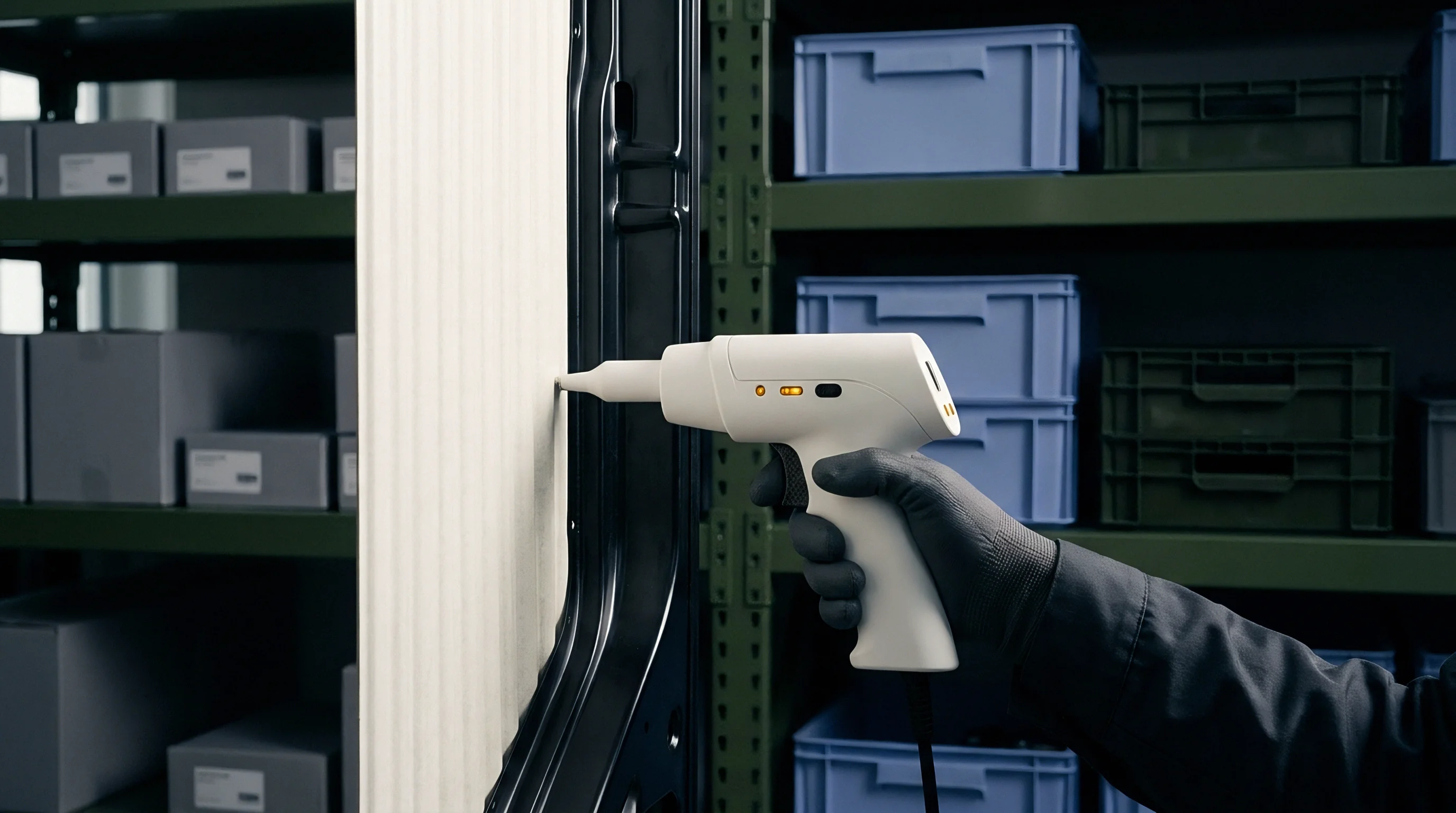
Shell
Installing an approved radio module inside a commercial enclosure alters the electromagnetic conditions established during bench testing. Manufacturers often buy wireless subassemblies carrying foreign grant identifiers under the belief that the paperwork passes straight through to the finished device. In an anechoic chamber, that assumption rarely holds up.
Housing materials, nearby DC-DC converters, dynamic trace impedance, and adjacent display flex cables all distort intentional radiation patterns as well as unintentional emissions. Legal compliance rests entirely on the finished hardware configuration, not the shielded module alone.
Standard plastic enclosures provide no attenuation against radiated energy.
Dielectric loading alters the resonance of internal PCB antennas, degrading return loss and pulling down total radiated power. If a plastic wall sits within three millimeters of an inverted-F trace antenna, the dielectric constant of polycarbonate can drag the center frequency downward by tens of megahertz. The output stage then drives into a mismatched load, driving up thermal dissipation and producing harmonic spikes that exceed statutory limits.
Conversely, placing that radio in a milled aluminum chassis with an external dipole creates chassis ground currents, turning structural seams into unintentional slot radiators.
A three-millimeter displacement between an integrated trace radiator and a structural polycarbonate housing shifts resonant frequencies by up to seventy megahertz.
Regulatory regimes treat modular approvals and full host certifications quite differently. In the United States under Federal Communications Commission rules, a modular grant spares an integrator from fundamental transmitter retesting only if the host design satisfies every restriction in the original filing. Canada follows a similar approach under Innovation, Science and Economic Development specifications.
European compliance under the Radio Equipment Directive works on a different principle: the European Union evaluates the finished product as a single unit, holding the economic operator who signs the EU Declaration of Conformity responsible regardless of any pre-tested subassemblies inside.
- Modular Grant Restrictions require strict adherence to the specific antenna types, trace layouts, and supply voltage tolerances documented in original laboratory filings.
- Chassis Ground Coupling pulls high-frequency clock noise from host processors into the RF ground plane, driving spurious emissions that fail unintentional radiator tests.
- Thermal Dissipation Limits restrict transmitter duty cycles whenever tight commercial enclosures limit airflow over power amplifier dies during long packet bursts.
- Firmware Lock Restrictions prevent end users from altering modulation schemes, operating frequency bands, or maximum conducted output power settings.
Hardware is often marketed as a drop-in solution needing no further regulatory work, on the premise that reference certificates satisfy cross-border border enforcement agencies without added laboratory expenses.


Drift
High-speed serial buses and power rails generate broadband noise that couples straight into adjacent radio transceivers. Switching supplies operating between 400 kilohertz and 2 megahertz cast harmonics into lower industrial, scientific, and medical bands. When these conducted disturbances mix with transmitter carrier frequencies, intermodulation products surface across previously clean spectrum.
Turntable scans during radiated spurious emissions testing under ETSI EN 300 328 or FCC Part 15.247 inevitably pick up these combined signals.
Spurious spikes easily rise above the thermal noise floor.
Pre-compliance bench testing on early production hardware helps catch RF degradation before committing to formal third-party chamber time.
- Place the unpowered host in a semi-anechoic chamber to establish ambient baseline noise across calibrated receiving antennas.
- Power the main digital board while keeping the radio dormant, measuring unintentional clock radiation and memory bus emissions up to 6 gigahertz.
- Trigger continuous transmit modes on low, middle, and high operational channels, plotting harmonic peaks against regulatory emission masks.
- Rotate the azimuth table through 360 degrees, alternating measurement antenna polarization between horizontal and vertical to find maximum field strength.
- Compare recorded margins against original module datasheets to quantify how host housing parasitics degrade emission baselines.
Uncontrolled ground loops readily act as broadband radiators.
Changing antenna geometry or picking a replacement with higher directional gain than the certified baseline voids the grant. A module approved with a 2.1 dBi omnidirectional dipole cannot legally run a 5 dBi patch antenna under the existing equipment authorization identifier. The higher gain increases equivalent isotropically radiated power, threatening statutory emission limits and human exposure ceilings.
Internal enclosure reflections also redirect conducted power into non-compliant radiated lobes.

Which Enclosure Modifications Trigger Radiated Spurious Retesting?
Switching an enclosure from flame-retardant plastics to carbon-fiber composites fundamentally alters internal RF behavior. Conductive inner walls set up cavity resonances that amplify certain sub-harmonics while dampening others. Moving a peripheral header, sinking a screw near an antenna trace, or shortening an internal ground spring alters the impedance seen by the power amplifier.
Such physical changes quickly erase compliance margins, turning clean pre-scan data into chamber failures.
Alterations to internal ground plane dimensions exceeding five percent of target operating wavelengths force full radiated spurious re-evaluations under international testing mandates.
Certification labs use targeted test routines to assess how mechanical changes shift conducted and radiated behavior across operating bands.
| Test Parameter | Reference Standard | Compliance Ceiling | Integration Trigger | Regulatory Action |
|---|---|---|---|---|
| Radiated Spurious Emissions | FCC Part 15.209 / EN 300 328 | 54 dBµV/m at 3 meters | Metallic bracket addition | Spot check chamber scan |
| Conducted Harmonic Distortion | FCC Part 15.247 / RSS-247 | -20 dBc relative to carrier | DC power trace re-routing | Conducted bench retest |
| Occupied Channel Bandwidth | ETSI EN 300 328 Clause 5.4.4 | Declared operating band | Antenna detuning shift | Class II permissive change |
| Chassis Unintentional Leakage | CISPR 32 / FCC Part 15B | Class B field limits | High-speed bus addition | Full host certification scan |
| Receiver Spurious Response | ETSI EN 301 489-17 | EN 55032 receiver limits | Display flex repositioning | EMC immunity re-evaluation |
Skipping chamber verification after mechanical updates risks customs seizures at import borders, triggering product recalls and stranded inventory across regional markets.

Check
Verification routes differ substantially between jurisdictions when integrating wireless modules into commercial products. In the United States, integrators following KDB 996369 must establish whether an enclosure design falls under Class I or Class II Permissive Change rules. A Class I change covers minor adjustments that introduce no measurable degradation in radiated profiles.
When trace dimensions shift or alternative antennas stay within the certified gain window, engineering records must prove baseline RF performance remains intact.
Chamber scans quickly expose unfiltered digital hash.
Class II Permissive Changes require submitting a formal technical filing to a Telecommunication Certification Body, complete with fresh radiated test data, revised schematics, and filing fees. The original FCC identifier may remain on the product label only if the original grant holder provides an official agent authorization letter. If the module supplier declines to sign, the host manufacturer must apply for an entirely new certification under its own FCC applicant code.
Board trace geometry determines final line impedance.
European compliance bypasses permissive change paperwork by assigning direct legal responsibility to the economic operator under the Radio Equipment Directive. Placing equipment on the market requires meeting core requirements for health, electrical safety, electromagnetic compatibility, and radio spectrum use. Standard ETSI EG 203 367 outlines testing protocols for multi-radio hosts and mechanical enclosures.
Instead of lodging test data with a central regulatory authority, the importer maintains a Technical Construction File on site, ready for inspection by market surveillance officials.
- Trace Antenna Boundary Integrity verifies that microstrip dimensions, board thickness, dielectric properties, and copper clearance zones match the original certified layout.
- Permissive Authorization Documents confirm written consent from the initial grant holder when lodging supplementary Class II dossiers with certification bodies.
- Unintentional Radiator Test Reports confirm that processors, display drivers, and power circuitry comply with statutory EMC ceilings under active clock operation.
- Declared User Guidance Records provide end users with mandatory RF exposure separation distances, operating band limitations, and regional installation requirements.
Test benches expose parasitic board-level coupling.
Engineering teams must evaluate certification pathways against these constraints before releasing production tooling.
Host manufacturers assuming regulatory custody without modular holder consent must re-execute fundamental radio chamber evaluations under an independent organizational equipment code.
Under ETSI EN 301 489-17 Clause 4.2.2, pairing an approved wireless module with an unshielded host board constitutes combined equipment, obligating the final manufacturer to run full radiated immunity and spurious emission sweeps across all concurrent operating modes.


Proximity
Bringing an active RF radiator within twenty centimeters of the body changes regulatory status completely. Most standalone module grants assume Mobile use, where antennas stay separated from operators by fixed distances. Installing that module into a handheld terminal, a wearable sensor, or an ear-level device pushes it into Portable classification.
Calculated Maximum Permissible Exposure figures no longer suffice; regulators require physical Specific Absorption Rate testing using tissue-simulating liquids.
Antenna detuning quickly saps radiated power.
Specific Absorption Rate testing quantifies RF dissipation inside body phantoms filled with liquid formulated to mimic human tissue dielectric properties. Transmitters operating between 4 megahertz and 6 gigahertz undergo spatial grid scans to record peak averages across one-gram or ten-gram tissue volumes. Enclosure ergonomics, battery location, and internal metal brackets tend to concentrate near-field energy into hot spots.
Even if a design clears free-space radiated power thresholds, localized absorption can easily breach the 1.6 watts per kilogram ceiling set by the FCC or the 2.0 watts per kilogram limit under CENELEC rules.

Will Co-Located Transmitters Invalidate Standalone Evaluation Grants?
Operating multiple transmitters at once complicates compliance beyond individual modular grants. When a cellular modem transmits alongside Wi-Fi and Bluetooth inside the same case, aggregate SAR ratios dictate approval. Individual grants evaluate each radio on its own, ignoring inter-antenna coupling.
If the sum of individual fractional exposure ratios exceeds unity, certification labs must run combined multi-band SAR scans to evaluate actual absorption fields.
Uncontrolled spatial proximity between co-located antennas and metallic battery casings elevates localized absorption metrics well beyond theoretical free-space calculations.
Shielding cans help contain harmonic bleed.
Hardware countermeasures such as thermal throttling, conductive foam gaskets, and algorithmic power reduction keep SAR within legal limits. Capacitive proximity sensors detect nearby skin and dial back transmit power by three to six decibels before limits are exceeded. Implementing dynamic power reduction complicates laboratory testing, as technicians must verify that power back-off lookup tables cannot be bypassed in production firmware.
Laboratory results leave unsettled whether coming millimeter-wave power density rules will allow modular approvals for wearable consumer devices once operational frequencies climb past ten gigahertz.

Transit
Customs checkpoints and regional agencies apply markedly different compliance rules at international borders. A valid United States FCC grant offers no standing in East Asia or Latin America. Japan mandates certification through Registered Certification Bodies under Ministry of Internal Affairs and Communications Radio Law statutes.
Even with an approved module, changing external antenna connections or enclosure shielding demands an updated Technical Regulations Conformity Certification, known throughout the industry as Giteki certification.
Border customs agents routinely audit certificate grants.
South Korea requires conformity testing managed by the National Radio Research Agency under KC certification rules. These standards enforce domestic EMC evaluations, requiring host hardware to pass testing inside accredited local facilities regardless of existing North American or European documentation. China takes a similar stance through the State Radio Regulatory Commission: SRRC type approval rejects foreign lab reports, demanding physical production samples at domestic test facilities to check frequency stability, occupied bandwidth, and spurious emissions.
In-country representatives carry direct legal liability.
Mismatched antennas instantly void modular grants.
In Latin America, Brazilian market clearance under ANATEL Resolution 715 requires designated certification bodies to examine technical construction files. Although ANATEL accepts modular pathways, the host product needs its own homologation certificate whenever enclosure geometry alters radiation patterns or internal power distribution differs from reference designs. Importers must either maintain an in-country corporate entity or contract a registered local representative to hold statutory responsibility for technical dossiers and consumer claims.
| Target Jurisdiction | Governing Agency | Modular Recognition Policy | Host Retesting Scope | Typical Approval Clock |
|---|---|---|---|---|
| United States | FCC | Permissive changes accepted | Part 15B unintentional EMC | 3 to 5 weeks |
| European Union | National Authorities | Self-declaration framework | ETSI EG 203 367 assessment | 2 to 4 weeks |
| Japan | MIC / Giteki | Strict construction rules | Spot radio and antenna check | 4 to 6 weeks |
| South Korea | RRA / KC | Limited module transferability | Local in-country EMC tests | 5 to 8 weeks |
| China | MIIT / SRRC | Fixed antenna designs only | In-country radio evaluations | 8 to 12 weeks |
| Brazil | ANATEL | Restricted radiation grants | Local laboratory testing | 6 to 10 weeks |
Product labeling faces physical inspection at ports of entry.
External markings must display exact regulatory symbols, grant codes, and statutory warnings required by local customs officials. Missing an FCC ID, an ISED certification number, or a Giteki mark on the enclosure can lead directly to customs impoundment. If housing dimensions make physical labeling illegible, electronic labeling within software menus is generally allowed under specific statutory criteria, provided that packaging materials supply clear navigation instructions.
Physical testing of the complete production housing ultimately determines whether a product gains legal market access across borders.