Radiated Spurious Emissions Mitigation in Multi Radio System Design
Radiated spurious emissions in multi-radio designs demand aggressive board-level isolation and predictive intermodulation filtering to secure market approvals.


Coupling
Transmitter leakage frequencies multiply inside non-linear junctions when two transceivers share an enclosure. Energy from a cellular power amplifier operating near 824 MHz traverses board ground planes, reaches the output stage of an adjacent 2.4 GHz Wi-Fi radio, and produces third-order intermodulation products falling directly into the 1575.42 MHz GPS L1 band. The resulting spurious emissions radiate through chassis apertures, antenna feedlines, and unshielded cable harnesses.
Regulatory authorities detect these products instantly because emissions in restricted bands face stringent radiated limits, frequently pegged at -41.2 dBm equivalent isotropically radiated power under standard FCC Part 15 rules or -36 dBm conducted power under European standards.
Co-located transceivers generate both active and passive intermodulation. Active mixing occurs directly inside the final stage transistor of an unselected transmitter when reverse isolation fails to suppress coupled forward power from an active neighbor. When a Bluetooth radio transmits at +10 dBm while a cellular transmitter puts out +23 dBm with 15 dB of antenna isolation, the Bluetooth output collector receives +8 dBm of cellular carrier energy.
That reverse signal mixes with the Bluetooth fundamental and its local oscillator leakages, generating sum and difference sidebands across dozens of megahertz.
A 6 dB rise in reverse-coupled transmitter power produces an 18 dB jump in third-order intermodulation amplitude at the victim antenna port.
Chassis boundaries and cable shields frequently transform into unintended antennas. Common-mode currents induced on a USB 3.1 Type-C flexible printed circuit board create parasitic dipole radiators that resonate at the harmonics of high-speed differential clocks. When these digital harmonics intersect the transmission bursts of an LTE Band 7 or Band 41 transceiver, intermodulation products bloom outward.
The laboratory antenna placed three meters away captures these composite emissions, registering sharp exceedances against general radiated limits.

Spectral Overlap in Multi Band Architectures
Simultaneous transmission multiplies the frequency combinations that an integrator must predict before booking chamber slots. A design integrating Sub-1 GHz LoRa, Bluetooth Low Energy, and quad-band cellular modules creates thousands of potential mixing products across the 30 MHz to 40 GHz compliance measurement window. Harmonic outputs from low-band transmitters frequently align with the fundamental reception or transmission windows of mid-band radios, causing receiver desensitization alongside illegal out-of-band emissions.
| Transmitter A Mode | Transmitter B Mode | Interaction Formula | Resulting Frequency (MHz) | Restricted Target Band |
|---|---|---|---|---|
| LTE Band 5 (835 MHz) | Wi-Fi 802.11b (2412 MHz) | 2f1 + f2 | 4082.0 | FCC 15.205 / 4.0 GHz Window |
| LTE Band 13 (782 MHz) | GPS L1 Receive (1575 MHz) | 2f1 | 1564.0 | GNSS Protection Band |
| Wi-Fi 802.11a (5180 MHz) | Bluetooth 5.0 (2440 MHz) | f1 – f2 | 2740.0 | Part 15 Restricted Band |
| ISM Band (915 MHz) | Wi-Fi 802.11g (2437 MHz) | 2f2 – f1 | 3959.0 | ETSI EN 300 328 Mask |
| LTE Band 4 (1732 MHz) | Wi-Fi 802.11b (2462 MHz) | f2 – f1 | 730.0 | Public Safety Allocation |
Failing to predict these mixing lines early forces complete printed circuit board respins, scrap production inventory, and voids six-figure pre-test investments.


Shield
Physical isolation stops radiated field collapse before cross-coupling contaminates sensitive transmitter networks. Solid stamped tin-plated steel or nickel-silver cans provide near-field boundary containment against magnetic and electric field vectors. A continuous solder perimeter anchors the can to the ground layer, establishing a closed Faraday boundary.
Openings in the metal work, including pick-and-place apertures and ventilation holes, act as slot antennas if their maximum dimension exceeds one-twentieth of the highest harmonic wavelength under review. At 10 GHz, this threshold limits aperture diameters to less than 1.5 millimeters.
Ground return paths govern the true effectiveness of any physical barrier. Signal currents seek the path of lowest impedance, which concentrates directly underneath transmission microstrips at radio frequencies. When split ground planes or ill-placed vias force return currents to detour around a barrier edge, current loops expand.
These loops turn internal ground planes into horizontal magnetic loop radiators that completely bypass surface cans.
Aperture Leakage and Cavity Resonance Behavior
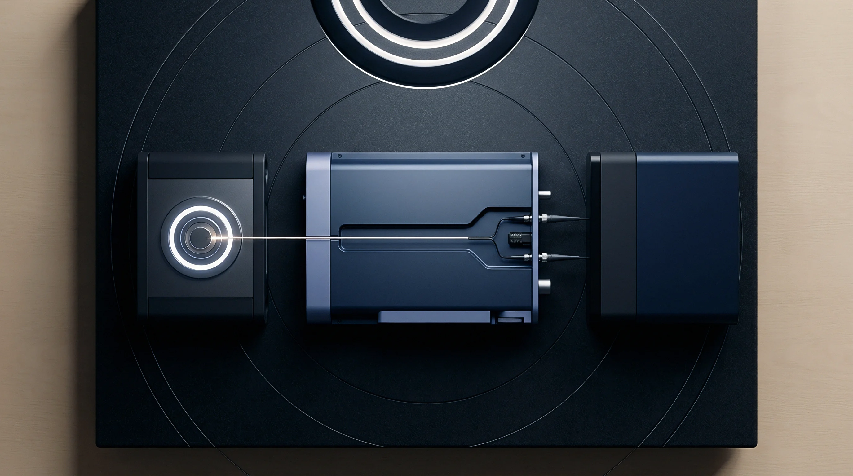
Enclosures house internal air volumes that form resonant resonant cavities at microwave frequencies. As clock speeds and radio harmonics push past 5 GHz, metallic housings with internal dimensions around 30 by 30 millimeters act as cavity resonators. Instead of attenuating radiated energy, an unlined metal housing amplifies specific harmonic frequencies through constructive standing wave patterns.
- Absorptive elastomeric sheets suppress standing wave buildup by converting high-angle microwave reflections into localized thermal dissipation along the interior ceiling.
- Conductive foam gaskets preserve unbroken electrical ground contact between removable module shields and exterior casting frames across thermal cycling regimes.
- Ground stitching via fences enforce minimum spatial isolation standards by maintaining center-to-center via separations no wider than two millimeters along plane edges.
- Partition walls within cans prevent direct magnetic cross-talk between baseband processor lines and high-gain low noise amplifiers.
Board-level isolation requires uncompromising mechanical design. Poor spring-finger contact creates invisible slot radiators. Gasket compression must remain uniform across all production tolerances to prevent edge radiation.
Shield boundaries function reliably only when ground continuity matches the highest frequency running beneath the can.


Filter
Direct frequency discrimination halts unwanted spectral emissions before conducted signals reach radiated structures. High-order ceramic bandpass, bulk acoustic wave, and thin-film bulk acoustic resonator architectures establish high rejection steepness within fractions of a percent of band edges. Inserting a miniature bulk acoustic wave filter into the Wi-Fi output line suppresses cellular Band 7 emissions by more than 45 dB, preventing active reverse intermodulation within the Wi-Fi front-end module.
These filters introduce insertion loss, consuming battery reserves while preserving regulatory margin.
Placement defines filtering efficacy. A filter situated thirty millimeters away from an amplifier output allows the intermediate transmission line to collect board noise via capacitive coupling, rendering the downstream rejection partially useless. Placing matching networks and filtering components within five millimeters of the radio frequency port eliminates stray pickup loops.
Differential lines running to balanced filters suppress common-mode currents that typically escape onto chassis surfaces.
What Drives Intermodulation in Passive Components?
Ferromagnetic materials in radio frequency pathways create surprising non-linearities at elevated power levels. Standard nickel surface plating on coaxial connectors, RF switches, surface-mount inductors, and trace plating acts as a weak diode junction under high current densities. When multi-watt transmitter signals pass through components containing magnetic nickel layers, third-order distortion products manifest directly inside the passive component body.
ETSI EN 301 489-1 limits non-radio auxiliary port emissions to 30 dB microvolts per meter in the 30 MHz to 1 GHz band, penalizing inadequate power line filtering.
Surface mount inductors near radio interfaces must use ceramic or non-magnetic cores. Ferrite beads selected for DC power rails generate measurable passive intermodulation if placed directly inside high-power antenna return lines. Soldering flux residue containing ionic contaminants creates microscopic non-linear leakage paths across closely spaced capacitor terminals.
Clean assembly procedures preserve filter attenuation boundaries.
| Technology | Typical Insertion Loss (dB) | Out-of-Band Rejection (dB) | Footprint Area (mm²) | Power Handling (W) |
|---|---|---|---|---|
| Surface Acoustic Wave | 2.2 to 3.5 | 35 to 45 | 1.4 x 1.1 | 1.5 |
| Bulk Acoustic Wave | 1.2 to 2.0 | 45 to 55 | 1.1 x 0.9 | 3.0 |
| Low Temperature Co-fired Ceramic | 0.8 to 1.8 | 20 to 30 | 2.0 x 1.2 | 5.0 |
| Thin Film BAW | 1.5 to 2.2 | 40 to 50 | 0.9 x 0.6 | 2.5 |
Suppliers routinely claim modular compliance figures apply to any host layout, disregarding the transmission line mismatch effects that destroy clean filter responses.


Turntable
Rotating an active multi-radio device inside a semi-anechoic or fully anechoic chamber exposes the true spatial distribution of radiated spurs. As the platform rotates through 360 degrees, the measurement mast traverses elevations between one and four meters, shifting between horizontal and vertical antenna polarizations. This complete spherical interrogation captures narrow, high-gain emission lobes that remain invisible during quick bench-level exploratory scans.
A single flexible antenna cable routing shift inside the device enclosure swings radiated peak values by 12 dB.

When Is Spot Checking Sufficient for Certification?
Full radiated retesting demands immense chamber hours, driving integrators toward regulatory spot-check paths. FCC KDB publication 996369 D04 permits spot-checking for hosts incorporating pre-certified modular transmitters, provided the host integrator proves co-location emissions stay below general Part 15.209 thresholds. The testing team configures all integrated transceivers to transmit simultaneously at maximum configured output power across worst-case operational bands.
Engineers record peak and average traces across the intermodulation frequencies calculated during pre-compliance analysis.
A three-meter radiated measurement across 1 GHz to 18 GHz demands a calibrated double-ridged horn antenna with preamplifiers maintaining noise figures under 3.5 dB.
Laboratory setup conditions dictate pass or fail outcomes. Battery-operated products must run on internal cell power rather than external switching bench supplies to eliminate conducted cable interference. Test software must exercise worst-case orthogonal axes.
If an integrated multi-radio asset tracker stands vertically in field deployment, horizontal chamber orientation testing alone invites regulatory audit rejection.
- Baseline single radio validation records the radiated spectrum for each individual transmitter operating alone at full rated power to document existing harmonic baselines.
- Simultaneous transmission configuration activates all cellular, satellite, short-range, and local-area transmitters through special vendor test mode firmware.
- Targeted frequency scan bands sweep narrow spans centered precisely on computed intermodulation combinations rather than relying solely on wide-span sweeps with low sweep times.
- Detector mode application evaluates suspect peaks using peak detectors initially, switching to CISPR quasi-peak below 1 GHz and average detectors above 1 GHz for final margin determinations.
According to FCC KDB 996369 D04 Section 3.2, host manufacturers bear unconditional legal responsibility for overall composite system compliance, invalidating any supplier marketing claims that modular certificates grant blanket host immunity.

Filing
Regulatory certification marks translate laboratory measurement reports into commercial distribution rights. In the United States, integrating two pre-certified radios without co-location approval requires either a Class II Permissive Change submitted by the original modular grantee or a completely fresh New Equipment Authorization filed by the host brand. The European Union Radio Equipment Directive 2014/53/EU demands an exhaustive composite technical dossier demonstrating adherence to essential requirements under Article 3.2, supported by Harmonised Standards ETSI EN 300 328, EN 301 893, and EN 301 489-17.
Global markets impose fragmented administrative barriers that defy single-pass laboratory validation. Japan relies on MIC Giteki approvals where multi-radio co-location assessments require explicit construction type certification annexes. South Korea mandates KC certification under National Radio Research Agency notices, demanding local in-country testing regardless of existing FCC or CE test dossiers.
China enforces SRRC radio approvals with mandatory testing conducted strictly inside mainland state-accredited laboratories, which review spurious limits down to -54 dBm across restricted public mobile bands.
| Jurisdiction | Authority | Modular Transfer Permitted | Typical Queue Time (Weeks) | Base Government Fees (USD) |
|---|---|---|---|---|
| United States | FCC / TCB | Yes (via Class II or KDB D04) | 2 to 4 | 1,200 to 2,500 |
| European Union | Notified Body / Self-DoC | Yes (Self-declaration route) | 1 to 3 | 0 (Self) / 3,000 (NB) |
| South Korea | RRA / KC | No (Host testing required) | 5 to 8 | 4,500 to 6,000 |
| Japan | MIC / RCB | Conditional on antenna gain | 3 to 5 | 2,800 to 4,200 |
| China | MIIT / SRRC | No (In-country active tests) | 8 to 14 | 5,500 to 9,000 |
Every additional market added to an expansion plan compounds schedule risk. Testing bottlenecks at state labs stall launches. Documentation translation errors cause customs seizures.
One single unchecked harmonic projection derails entire release schedules.
The unresolved question remains whether international harmonization bodies will ever standardize co-located intermodulation evaluation protocols before rising component densities render traditional external chamber testing economically impossible.