Validation Procedure for Phased Array RF Exposure Compliance
Phased array RF exposure compliance combines robotic near-field power density scans with FDTD simulations and dynamic power-tracking algorithm validation.

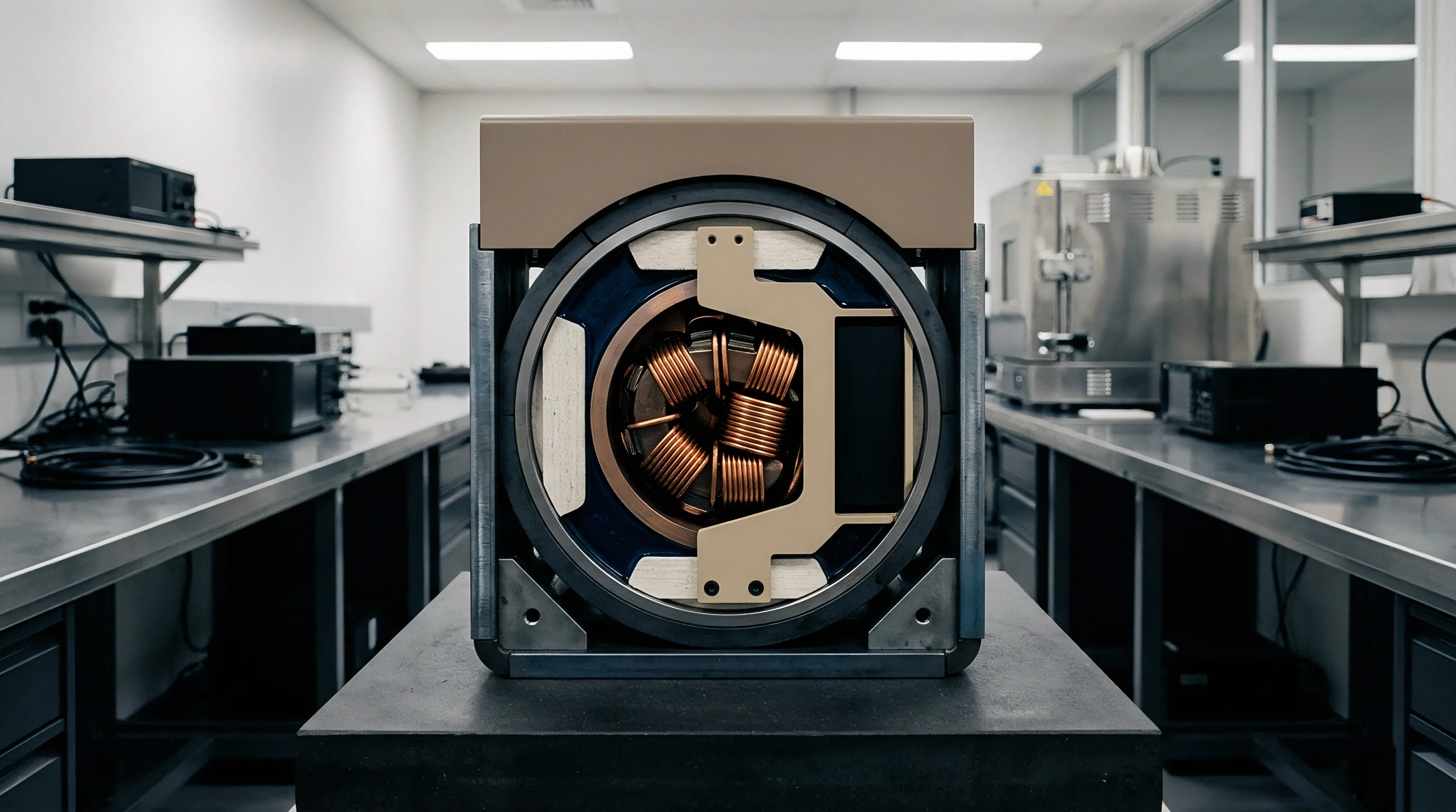
Chamber
Millimeter-wave arrays operating above 24 GHz omit conducted coaxial ports entirely, forcing compliance evaluations into over-the-air radiated environments. Regulators across the United States, Canada, Europe, and South Korea assess exposure here using incident power density rather than specific absorption rate. The transition boundary sits at 6 GHz under Federal Communications Commission rules and 10 GHz under International Commission on Non-Ionizing Radiation Protection 2020 guidelines, placing modern fifth-generation arrays squarely under power flux density metrics.
The primary compliance parameter is spatial peak incident power density averaged over a defined surface area ~ typically 4 square centimeters for general public settings, alongside a 1 square centimeter evaluation surface specified under international harmonized standards. Test houses position the active device on a low-permittivity foam turntable inside an anechoic enclosure lined with pyramidal carbon-loaded absorbers rated to minus 40 decibels of reflectivity at 40 GHz.
Physical scans require millimeter-level positioning accuracy. A robotic articulation arm moves an isotropic pseudo-vector or field probe across a planar evaluation surface at the manufacturer’s declared separation distance ~ typically 2 millimeters for smart mobile devices and 5 millimeters for portable computing hosts. The probe follows an adaptive spatial grid with step sizes capped at one-quarter wavelength at the highest operating channel frequency.
At 39 GHz, one-quarter wavelength equals 1.92 millimeters, requiring positioning repeatability within 0.1 millimeters across all three orthogonal axes.
The array uses sixteen dual-polarized patches.
The probe holds five millimeters.
Sweeping an entire codebook through mechanical surface scans creates severe laboratory backlogs. An active 5G beamforming module integrates dozens to hundreds of predefined phase and amplitude vector pairings stored in firmware registers. Measuring every phase configuration over six device surfaces at fine grid resolution consumes upwards of eight hours per beam state.
The standard validation workflow defined under IEC/IEEE 63195-1 bypasses this bottleneck by combining full physical scans of selected worst-case beam states with numerical modeling reconstructions. Laboratories execute a fast area scan using electro-optic sensor arrays or distributed reconstruction grids to locate spatial maximums, followed by high-density volume scans centered over the peak field regions.
Incident power density averaging over four square centimeters yields a regulatory ceiling of ten watts per square meter under Federal Communications Commission limits for portable transmitters.
Evaluating radio frequency exposure for array systems requires total field vector assessments. Polarization ellipse parameters and phase differences between orthogonal antenna elements dictate whether incoming wave fronts combine constructively at the measurement grid. The scan system captures tangential and normal electric field components, using phase-reconstruction algorithms to back-propagate measured fields to the device surface.
Phase drift caused by transmitter thermal heating during protracted chamber dwell times invalidates this reconstruction. Laboratories monitor conducted reference couplers or calibrated receive horns positioned in the chamber back-lobe to normalize RF drift, aborting scans whenever source power shifts beyond 0.5 decibels.
The fee reaches six thousand dollars.
Chamber time costs eight hundred dollars hourly.
Omitting thermal stabilization monitoring during radiated scans produces artificial power drops that cause certified test bodies to reject exposure dossiers during audit screenings.


Computation
Electromagnetic field solvers running the Finite-Difference Time-Domain method calculate near-field energy distribution directly from computer-aided design files of the housing, transmission lines, and antenna substrate. This calculation requires realistic dielectric property assignments for every mechanical layer: the display stack, glass backing, copper heat spreaders, and metallic chassis frame. Grid resolutions finer than one-twentieth of the guided wavelength resolve microstrip feedlines and patch radiator edges, driving simulation meshes past 400 million cells for a standard smartphone enclosure.
Modeling tools compute both Poynting vector magnitude and its complex spatial distribution across evaluation surfaces positioned at distances from 2 millimeters to 150 millimeters from the enclosure exterior.
The simulation output forms the definitive beam codebook compliance matrix. For every targeted band, such as n257, n258, n260, or n261, the software calculates total radiated power, equivalent isotropically radiated power, and spatial peak power density across all defined phase pairings. The critical output is the ratio of simulated maximum power density to conducted array input power, generating the exposure-to-power scaling factor known as the beam-specific conversion factor.
Regulators require applicants to demonstrate that this computational tool predicts physical hardware performance with traceable fidelity.
The scan takes forty minutes.

Does Numerical Modeling Replace Turntable Measurements?
Validation protocols established by international consensus standards mandate strict correlation between physical measurements and numerical predictions before simulation results can enter an official filing. Testing calls for a minimum of three distinct beam configurations per active array module: the maximum directional beam, a steered beam at the 3-decibel scan limit, and a distributed cross-polarized configuration. The applicant runs both physical scans and computational simulations for these baseline states.
Agreement between measured and computed peak spatial power density distributions must fall within the uncertainty budget set by standard test procedures.
| Validation Parameter | Acceptance Criteria | Reference Condition | Consequence of Deviation |
|---|---|---|---|
| Peak Power Density Location | Spatial offset under 2.5 mm | 4 square centimeter averaging at 5 mm separation | Re-mesh structural dielectric boundaries |
| Absolute Peak Value Difference | Deviation under 1.2 dB | Continuous wave drive at nominal maximum conducted power | Recalibrate component substrate dielectric loss tangents |
| Two-Dimensional Enclosure Correlation | Normalized cross-correlation over 0.85 | Planar grid spanning two wavelengths beyond antenna aperture | Re-execute physical scan with fine mechanical alignment |
| Linearity Across Drive Levels | Linear deviation under 0.3 dB | Conducted sweep across 10 dB input range | Inspect power amplifier compression modeling tables |
Failing to achieve correlation across these parameters triggers a full audit of structural CAD models. Small deviations in manufacturing tolerances ~ including solder mask thickness on patch surfaces, display bezel adhesive conductivities, and ground spring contact impedances ~ shift beam tilt angles by several degrees. A three-degree phase error at 28 GHz shifts the localized peak power density location by more than 3 millimeters, breaching the correlation envelope and invalidating the simulation baseline.
Section 4.3 of IEC/IEEE 63195-2 mandates that simulated spatial power density distributions match physical chamber measurements within an expanded uncertainty margin of 1.6 decibels.
Uncertainty analysis pools contributions from mechanical grid meshing, numerical truncation boundaries, material property tolerances, and source modeling approximations. Standard uncertainty for the computational stage routinely tallies between 15 and 25 percent. Adding physical measurement probe uncertainty of 10 to 18 percent yields an expanded validation uncertainty that the manufacturer must deduct directly from regulatory ceilings.
An applicant with an unoptimized validation file may find operational transmit power capped 2 decibels below hardware limits simply to absorb unquantified variance between codebook simulations and chamber verification.
The dipoles read three percent low.
How far manufacturing tolerances in antenna package substrates distort simulated near-field Poynting vectors remains an open inquiry across high-volume production runs.


Algorithm
Modern mobile platforms integrate dynamic exposure moderation firmware, commonly referenced under proprietary architectures such as Smart Transmit or Time Average SAR and Power Density controls. These algorithms govern instantaneous output power in real time, calculating running time-averaged exposure across sliding windows defined by statute. In the United States, the FCC specifies a 100-second averaging window for frequencies below 3 GHz, a 60-second window between 3 GHz and 6 GHz, and a 4-second averaging window for millimeter-wave bands above 24 GHz.
When an array transmits, the algorithm integrates current power levels across the preceding 4-second block, scaling back conducted output power before the normalized exposure budget reaches unity.
Validating runtime exposure managers requires specialized radio communication testers equipped with base station emulation, digital sampling cards, and bidirectional RF power couplers. The test sequence executes transient conducted power measurements while stepping the device through controlled call states. The testing station commands beam switches, transmit power control escalations, component carrier additions, and link drop transitions to verify that firmware halts power output precisely at the calculated compliance threshold.
The test houses run two shifts.
The limit remains ten watts per square meter.

Do Time Averaging Algorithms Hold under Rapid Handover?
Transitions between sub-6 GHz cellular links and millimeter-wave array beams represent the most stringent algorithmic validation test. Exposure contributions from both domains must sum to an aggregate ratio that never exceeds 1.0 across overlapping evaluation periods. The test apparatus configures an active Long Term Evolution or 5G Sub-6 link operating simultaneously with a 28 GHz carrier.
As path loss on the high-frequency link rises, the tester commands the millimeter-wave transmitter to escalate conducted power until it approaches the calculated thermal budget, at which point the algorithm must automatically depress lower-frequency transmitter output power or shed millimeter-wave beams entirely.
- Baseline power level initialization establishes steady-state operation below the regulatory exposure threshold on all active frequency bands.
- Radio link path loss step escalation commands instantaneous maximum output power from the device to sustain receiver sensitivity.
- Real-time power tracking logging records the exact millisecond-by-millisecond conducted output profile through calibrated power sensors.
- Algorithmic backoff execution throttles millimeter-wave power as the calculated cumulative exposure sum reaches ninety-five percent of the statutory limit.
- Normalized exposure ratio calculation aggregates time-averaged SAR and power density traces to prove the combined metric remains beneath unity.
Validation procedures require evaluating multiple beam index switching profiles. Test engineers program the base station emulator to trigger beam handovers every 100 milliseconds across diverse spatial configurations, driving the array through its complete phase set. The firmware tracking engine must calculate running integrals accurately during rapid beam steering without exhibiting lag or arithmetic overflow errors.
An algorithm that under-reports transient power spikes during beam steering permits localized field concentrations that exceed human exposure safety thresholds.
A transmission system managing simultaneous sub-6 GHz and millimeter-wave radiation bounds aggregate exposure by enforcing a normalized summation ratio strictly below 1.0.
Lead time stretches four weeks.
Proprietary firmware execution limits are designed to prevent exposure overshoots under all operating scenarios, yet laboratory scans demonstrate control loop lag during sudden cell dropouts.
Ledger
Equipment authorization filings containing phased array modules present some of the thickest compliance exhibits submitted to Telecommunication Certification Bodies. Administrative filings cannot rely on standardized modular grant references whenever antenna structures or algorithmic parameters depend on host chassis integration. The complete dossier comprises the radio frequency exposure simulation report, physical measurement validation document, uncertainty budget accounting report, operational description of the exposure mitigation algorithm, and test plan correlation matrix.
Every document must map directly to FCC KDB 842590 D01 procedures or Innovation, Science and Economic Development Canada SPR-003 and SPR-004 specifications.
Regulators scrutinize the relationship between theoretical codebooks and factory calibration routines. Test laboratories assemble extensive compliance tables documenting maximum conducted power levels, equivalent isotropically radiated power ceilings, and worst-case spatial peak power density values for every supported frequency band and beam state index. Filings encompassing dual-module millimeter-wave installations routinely carry data points numbering in the tens of thousands.
The draft report arrives in ten business days.
The engineer signs the attenuation sheet.
- Antenna pattern manufacturing tolerance tables document permissible gain and phase variances across high-volume surface-mount array lots.
- Dielectric substrate permittivity verification sheets confirm high-frequency material properties through split-cylinder cavity resonance tests.
- Algorithmic look-up tables define the maximum input power ratings allowed for every distinct beam identification code.
- Host integration mechanical drawings delineate precise clearance distances between patch elements and inner housing surfaces.
Uncertainty budgets must account for every experimental and numerical variable. Measurement instrumentation uncertainty captures probe isotropy, absolute calibration errors, scan system positioning repeatability, and RF detector linearity. Simulation uncertainty quantifies mesh density convergence, boundary reflection artifacts, dielectric loss uncertainties, and geometric CAD simplifications.
Cumulative uncertainty determines the compliance margin that must separate maximum evaluated field levels from statutory limits.
| Uncertainty Contributor | Probability Distribution | Divisor | Standard Uncertainty (dB) |
|---|---|---|---|
| Field Probe Calibration | Normal (k=1) | 1.0 | 0.35 |
| Probe Isotropy and Linearity | Rectangular | 1.732 | 0.28 |
| Robotic Positioning Repeatability | Rectangular | 1.732 | 0.12 |
| Chamber Reflections and Scattering | Rectangular | 1.732 | 0.40 |
| Numerical Meshing Convergence | Normal (k=1) | 1.0 | 0.30 |
| Housing Material Dielectric Constant | Rectangular | 1.732 | 0.25 |
| Expanded Uncertainty (k=2) | Normal | N/A | 1.48 dB |
The housing carries three millimeter walls.
FCC KDB Publication 842590 D01 mandates that applicants demonstrate algorithmic exposure stability across all operating configurations, revoking the certification grant if undocumented host alterations increase spatial peak power density.

Release
Market delivery of devices housing steerable millimeter-wave arrays hinges on sequencing laboratory reservations against commercial product launch milestones. Lead times for specialized millimeter-wave chamber access extend to six or eight weeks during peak pre-launch seasons, with testing campaigns spanning three to five weeks per variant. The testing cost for a platform integrating two millimeter-wave antenna arrays alongside sub-6 GHz radios ranges between 45,000 and 80,000 dollars, excluding engineering retest fees and computational simulation modeling expenses.
Missing a scheduled chamber window or failing an algorithmic test scenario delays market entry dates, idling factory assembly lines and incurring warehouse holding costs.
Securing an initial equipment authorization grant does not conclude exposure compliance obligations. Production manufacturing requires ongoing surveillance to confirm that component supplier shifts do not degrade exposure metrics. Swapping an antenna module supplier, altering housing resin polymers, or updating power management firmware triggers permissive change regulations.
In the United States, alterations that increase radiated emissions or change the RF exposure profile require a Class II Permissive Change filing, complete with supplemental test reports, chamber scans, and regulatory certification body approvals.
The test sample requires dedicated test firmware.
Engineers must institute strict change control protocols covering housing resins, antenna package substrates, and power control algorithms to protect grant validity. When firmware developers modify beam-switching look-up tables to enhance link stability, the change frequently increases peak incident power density on peripheral beams. A single undocumented firmware update deployed to retail units that elevates RF exposure above certified limits creates non-compliance liabilities, prompting customs detentions and regulatory enforcement actions across global sales jurisdictions.
A production component substitution shifting dielectric permittivity by more than five percent demands fresh chamber validation to defend the existing market authorization.
Host integration challenges multiply when modular assemblies are supplied to third-party enclosure manufacturers. Modular grants for millimeter-wave phased arrays remain severely restricted under FCC rules, since changes in external host casing material, display wiring, or battery placement reshape the near-field Poynting vector distribution. Integrators cannot rely on simple modular declarations, facing the expense of full host-level exposure authorization filings for every distinct physical form factor.
Chamber data and simulation files reveal the realities that glossy marketing declarations gloss over.