Meaning
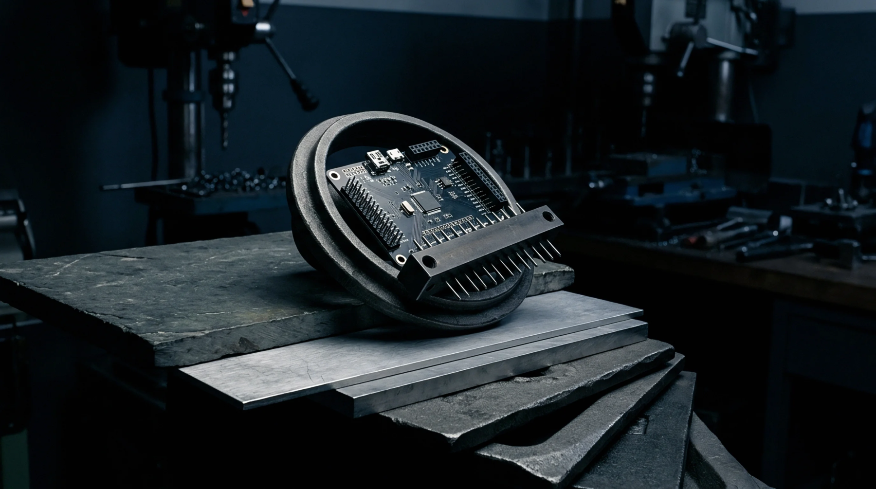
Electrical interface components establish separable interconnections between two printed circuit boards without the use of cabling. These board to board connectors permit the transfer of high-speed digital signals and power across multi-board systems. They are designed to withstand mechanical tolerances and thermal expansion while maintaining low contact resistance.
Their use is standard in compact modules where space is constrained, allowing engineers to partition a complex design into smaller, testable sub-modules. This modular approach simplifies manufacturing and debugging by allowing individual cards to be swapped out easily.
Mechanical Alignment
Physical alignment during the mating process remains a primary consideration for multi-board assemblies. When board to board connectors are paired, they rely on built-in guide pins or chamfered housings to correct for minor offsets. Rigid mounting can lead to stress build-up, which is why some designs incorporate floating contacts to absorb up to half a millimeter of movement.
This flexibility prevents micro-cracks in the solder joints.
Signal Integrity
High-speed data transmission requires careful control of impedance and shielding across the interface. The contact geometry of board to board connectors is engineered to match fifty-ohm line requirements. Return loss is kept minimal through dedicated ground pins.
This shielding ensures clean communication.
Thermal Budget
Heat dissipation across the mated interface depends heavily on contact force and material selection. In heavy-duty assemblies, board to board connectors must handle continuous power without exceeding the maximum operating temperature of the housing polymer. High-conductivity copper alloys with gold plating are typically selected to minimize resistive heating at the contact point.
This choice ensures long-term reliability under sustained electrical loads.