Meaning
Specialized radio frequency sensors measure aggregate electric or magnetic field strengths uniformly without regard to the spatial polarization of the incoming electromagnetic wave. An isotropic probe integrates multiple orthogonal sensor elements into a single small cluster to achieve a non-directional spherical reception pattern. The device operates as the core field sensor in specific absorption rate testing systems and electromagnetic hazard evaluations.
Physical accuracy drops off when field frequencies exceed the upper resonance cutoff of the internal dipole elements or when field gradients change radically across the sensor tip dimensions.
Sensor Array
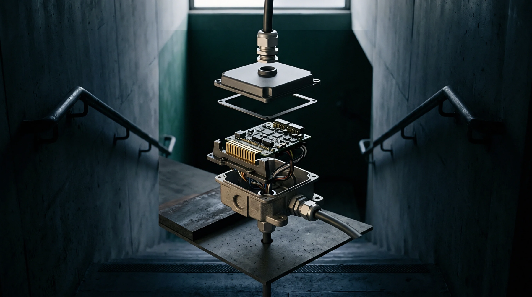
Three miniature dipole or magnetic loop sensors align along mutually perpendicular axes to collect three-dimensional field components. Each miniature antenna couples directly to a dedicated beam-lead Schottky diode or optical modulator situated at the probe tip. The mechanical layout packs these sensors into a narrow dielectric enclosure to minimize field perturbation inside simulated biological liquids.
Sensor lines travel away from the active tip using high-resistance leads to suppress unwanted radio frequency currents along the probe shaft. The vector magnitude combines the squared outputs of all three axes to deliver an omnidirectional field measurement.
Polarization Independence
Planar emission fields from internal terminal antennas exhibit complex, elliptical polarizations that change with chassis orientation. An isotropic probe samples arbitrary polarization states accurately without requiring mechanical rotation around its axis. Deviations from an ideal spherical pattern generate probe isotropy errors, which must be tracked and bounded during calibration cycles.
Standard calibration routines rotate the probe within a known plane-wave field to map axial and hemispherical response variations. Certified instruments hold total isotropic deviation within a fraction of a decibel across their rated bandwidth.
Field Gradient
Spatial resolution limits appear when field strengths decay steeply across the millimeter physical boundary of the sensor head. Dipole elements evaluate average energy across their physical lengths, which underestimates localized field peaks generated near surface boundaries. Mathematical gradient compensation functions apply post-processing corrections to measured data based on the physical separation between sensor elements and the probe tip shell.
The measurement protocol enforces a minimum mechanical clearance distance from phantom boundaries to avoid capacitive loading between the probe tip and the enclosure material. Probe calibration certificates verify physical offsets used by automated scanning routines.