Meaning
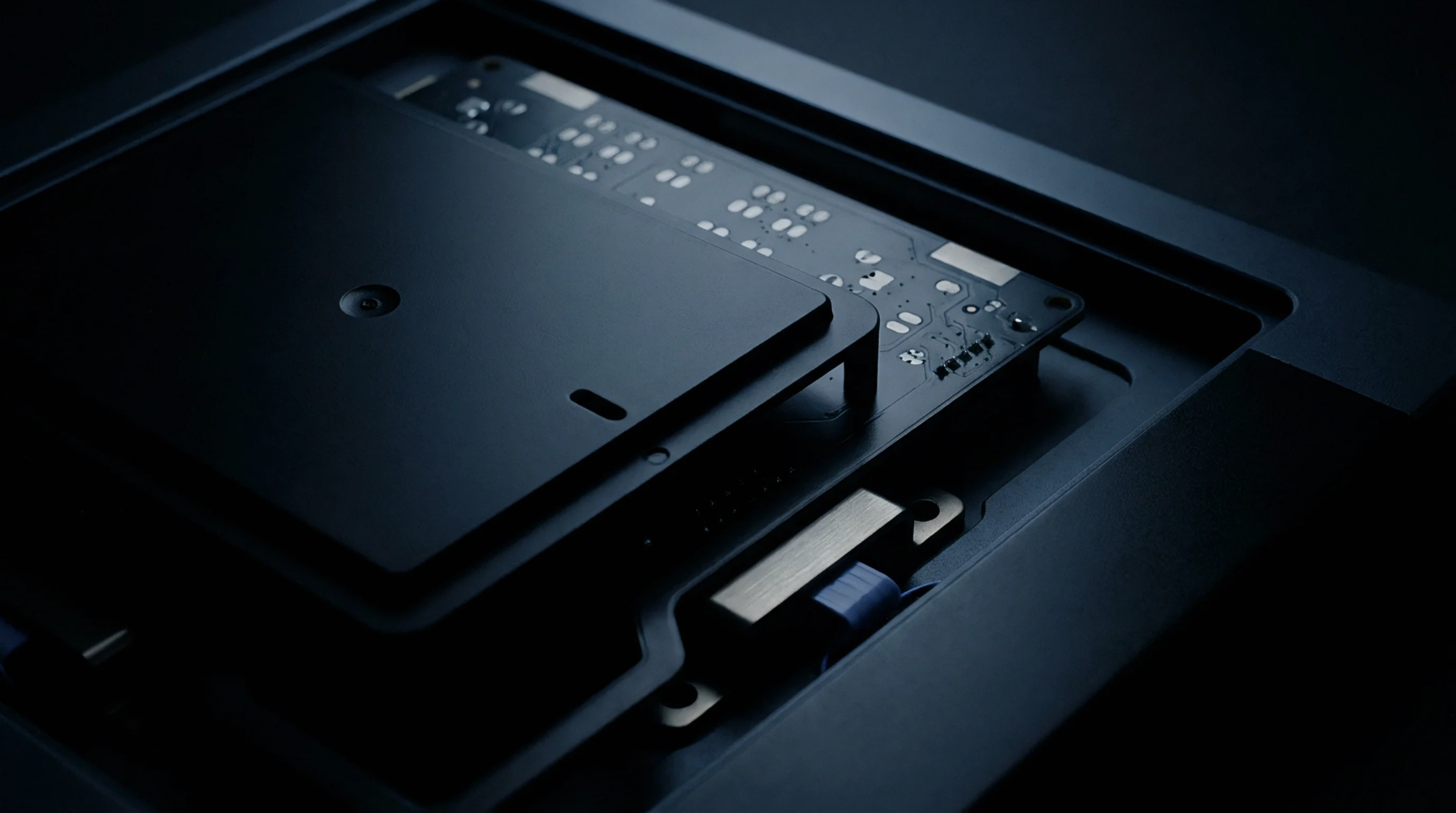
Physical assembly hardware aligns printed circuit boards to electrical probes or communication ports for rapid validation. A test jig acts as the mechanical host that holds a unit under test in a fixed orientation to ensure repeatable contact between signal pins and internal circuitry. It bridges the gap between high volume manufacturing lines and individual component inspection requirements.
Proper alignment minimizes transient contact faults during automated functional checks.
Interface Verification
Precision positioning prevents structural damage to fragile connectors or delicate board layouts when pressure engages the test array. Operators lock the device into a cradle that directs force along specific axes to maintain impedance stability during signal transmission. Consistent grounding throughout this mechanical engagement reduces noise injection from the external diagnostic environment.
Production Reliability
Calibration cycles govern the frequency of physical maintenance performed on these holding fixtures to compensate for wear on spring-loaded pins. Gradual degradation of contact surfaces alters the resistive measurement of the device signals by introducing parasitic impedance that masks legitimate failures. Frequent inspection of the alignment plate prevents cumulative errors in mass production where small shifts propagate across thousands of components.
Fixture Design
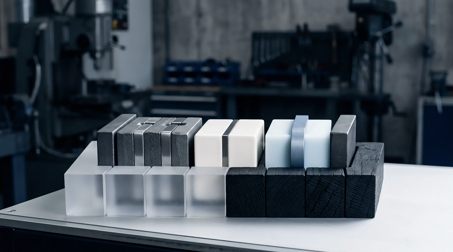
Custom mechanical enclosures accommodate specific board geometries and clearance requirements defined during the initial hardware development phase. Designers select materials like high density polymers or reinforced composites to ensure thermal stability while the unit generates heat during high speed logic execution. Thermal expansion must fall within defined tolerances to prevent the test jig from losing signal registration as internal temperatures rise.