Evaluating Simultaneous Transmission Compliance for Multi Radio Module Host Integrations
Host multi radio compliance relies on spatial antenna isolation, intermodulation suppression, and summed SAR exposure ratio evaluation before filing.


Overlap
A cellular module transmitting at 23 dBm on 835 MHz alongside an 18 dBm 2.4 GHz Wi-Fi radio sets up simultaneous electromagnetic fields within the same chassis. Operating multiple RF transceivers in close proximity forces their radiating elements to interact across both near and far fields. Physical spacing determines whether this radiated energy combines constructively or destructively throughout the enclosure.
Antenna interaction is governed by separation distance, board routing, and structural geometry. Modules integrated into multi-radio hosts regularly share ground planes or sit against common metal brackets, offering conductive paths that channel coupled RF energy straight into neighboring front-end circuits. When distance between antenna feeds narrows, mutual coupling climbs sharply.

Spatial Spacing and Antenna Coupling Parameters
Allowing less than five centimeters of physical clearance on a shared printed circuit board degrades RF isolation below fifteen decibels. Transceivers tied to an unbroken ground plane induce surface currents that erode receiver sensitivity on both operating channels. Strong coupling then drives power from one active transmitter directly into the output matching network of the other.
A 10 dB decrease in antenna isolation increases intermodulation power by 20 dB when dual transmitters operate at full rated power.
Designers damp standing waves with absorbing materials and track isolation through scattering parameters, focusing on port-to-port insertion loss. Maintaining twenty decibels of isolation protects power amplifiers from saturation and limits spurious mixing inside front-end hardware.
| Radio Pair | Frequency Separation | Minimum PCB Distance | Measured Coupling (S21) | RF Exposure Interaction |
|---|---|---|---|---|
| Cellular Sub-6 GHz and Wi-Fi 2.4 GHz | 1.55 GHz | 35 mm | -22 dB | Low Near-Field Coupling |
| Wi-Fi 2.4 GHz and Bluetooth LE | 10 MHz | 15 mm | -12 dB | High Mutual Near-Field Summation |
| Cellular Sub-6 GHz and LoRaWAN 915 MHz | 80 MHz | 45 mm | -18 dB | Moderate Conductive Ground Coupling |
| Wi-Fi 5 GHz and Wi-Fi 6 GHz | 850 MHz | 20 mm | -16 dB | Localized Field Concentration |
Field Summation for near Field Exposure
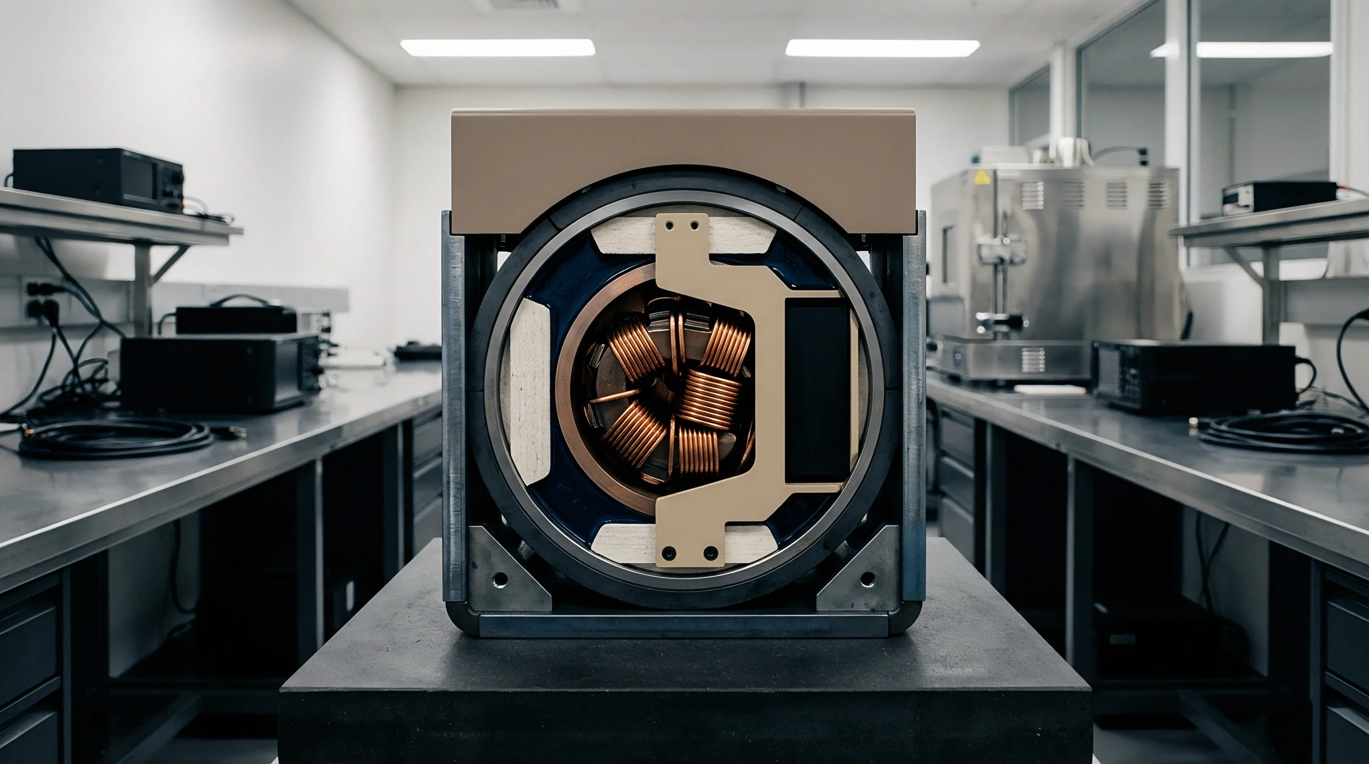
Specific absorption rate testing records energy absorbed by tissue phantom models while transceivers broadcast at full rated power. For portable devices operating within twenty centimeters of the human body, these fields combine directly in tissue.
Near-field interactions alter local electric and magnetic field distributions relative to what isolated module certifications show. Vector summation can create localized exposure peaks that exceed standalone compliance ratings.
- Conductive Ground Plane Coupling RF current flows through shared copper return paths to modulate adjacent RF front-end LNAs.
- Radiated Near Field Enclosure Resonance Metal internal shields form resonant cavities that concentrate electromagnetic density near low-noise amplifiers.
- Harmonic Vector Re-radiation Power amplifier output filters fail to attenuate second harmonics that fall directly into secondary radio receiver passbands.
- Thermal Drift Induced Detuning Concentrated heat from concurrent power amplifiers shifts antenna matching network impedance away from 50 ohms.
Inadequate spatial isolation between active antennas forces full SAR lab evaluations, adding six weeks and fifteen thousand dollars to host hardware certification schedules.

Spur
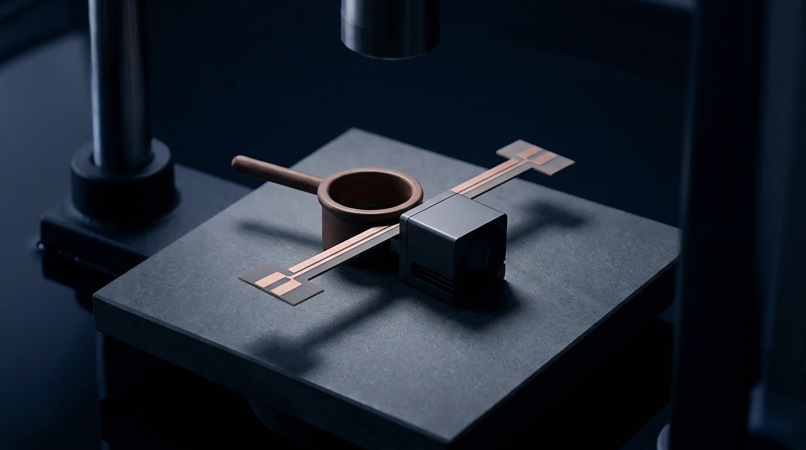
Nonlinear active components generate out-of-band mixing products whenever two radios broadcast simultaneously. Output stages, switches, and poorly bonded mechanical joints all behave as mixers under elevated RF drive levels.
Transmitter interaction produces spurious emissions at predictable mathematical intervals. Third-order intermodulation products present the greatest operational hazard because their frequencies frequently fall inside an active receiving band.

Intermodulation Generation inside Front End Amplifiers
High-level RF energy entering an adjacent antenna travels backward through the power amplifier directional coupler. Once inside the nonlinear output stage, this injected signal mixes with the primary transmit carrier, generating spurious sidebands that re-radiate from the secondary antenna.
Compliance with FCC Part 15.247 harmonic limits does not guarantee passband integrity when concurrent cellular power amplifier mixing occurs on shared PCB traces.
Designers insert high-rejection bandpass filters and shielding between the power amplifier and antenna matching network to block out-of-band energy from reaching the output stage. Attenuating reverse power by fifteen decibels suppresses third-order intermodulation distortion by forty-five decibels.
| Primary Transmitter | Secondary Transmitter | Target Passband | Intermodulation Formula | Typical Level |
|---|---|---|---|---|
| LTE Band 4 (1720 MHz) | Wi-Fi 2.4 GHz (2412 MHz) | GPS L1 (1575.42 MHz) | 2f1 – f2 (1028 MHz) / f2 – f1 | -65 dBm |
| LTE Band 13 (782 MHz) | Wi-Fi 2.4 GHz (2437 MHz) | Public Safety (700 MHz) | 2f1 – f2 (1127 MHz) | -52 dBm |
| Wi-Fi 2.4 GHz (2462 MHz) | Bluetooth (2402 MHz) | Wi-Fi Passband | 2f1 – f2 (2522 MHz) | -48 dBm |

Receiver Desensitization from Concurrent Radiation
Broadband cellular emissions bleeding into nearby unlicensed spectrum raise the noise floor of sub-gigahertz receivers. This elevated ambient energy overloads the low-noise amplifier and pushes the front end into compression.
Cross-modulation impresses the amplitude envelope of a strong interferer onto a weaker target carrier. Installing high-Q surface acoustic wave filters at receiver inputs keeps strong out-of-band signals from swamping the front end.
Modular certifications assume isolated operation, yet physical proximity inside a host enclosure shifts radiated harmonic power well beyond baseline grant conditions.


Margin
Regulatory frameworks enforce cumulative exposure thresholds to constrain energy absorption from multi-radio systems. Every active transmitter contributes a proportional share toward the total exposure budget.
Evaluations rely on normalized ratios for both Specific Absorption Rate and Maximum Permissible Exposure. Provided the sum of all concurrent exposure ratios remains at or below 1.0, the host complies with applicable safety limits without requiring physical phantom testing.

Maximum Permissible Exposure Ratio Calculations
Transmitters separated by more than twenty centimeters are assessed using far-field power density calculations. This analytical approach models exposure directly, with power density scaling by effective isotropic radiated power over inverse-square distance.
When evaluating a host with co-located LTE, Wi-Fi, and Bluetooth links operating simultaneously past twenty centimeters, each calculated power density is divided by its frequency-specific exposure limit. A standard enterprise gateway operating three simultaneous transceivers illustrates the arithmetic:
Transceiver 1: LTE Band 5 operating at 836.5 MHz with 23 dBm output power and 2 dBi antenna gain (316 mW EIRP). At 20 cm distance, calculated power density equals 0.063 mW/cm². The FCC MPE limit at 836.5 MHz equals f/1500, or 0.558 mW/cm².
The exposure ratio equals 0.063 / 0.558 = 0.113.
Transceiver 2: Wi-Fi 2.4 GHz operating at 2437 MHz with 20 dBm output power and 3 dBi antenna gain (200 mW EIRP). At 20 cm, power density equals 0.040 mW/cm². The MPE limit at 2.4 GHz equals 1.000 mW/cm².
The exposure ratio equals 0.040 / 1.000 = 0.040.
Transceiver 3: Wi-Fi 5 GHz operating at 5785 MHz with 18 dBm output power and 4 dBi antenna gain (158 mW EIRP). At 20 cm, power density equals 0.031 mW/cm². The MPE limit at 5.785 GHz equals 1.000 mW/cm².
The exposure ratio equals 0.031 / 1.000 = 0.031.
Summing the three exposure ratios yields 0.113 + 0.040 + 0.031 = 0.184. Because 0.184 sits well below the maximum limit of 1.0, the host satisfies mobile RF exposure requirements.
Maintaining total exposure ratios below unity allows host integrators to skip physical phantom SAR lab measurements.

Specific Absorption Rate Exclusion Limits and Ratios
Portable devices operating within twenty centimeters of the body rely on test exclusion thresholds keyed to power output and separation distance. FCC KDB 447498 D01 sets the specific power cutoffs under which physical SAR testing can be waived.
When radiated power crosses that threshold, lab testing becomes mandatory. Measured SAR values normalized against the 1.6 W/kg limit produce individual ratios that must be summed across every simultaneous transmitter.
- Determine the maximum time-averaged output power and source-based duty cycle for each integrated radio module.
- Measure physical separation distances between all co-located active antennas and the outer host enclosure surface.
- Calculate individual exposure ratios for each transmitter using regulatory specific absorption rate equations.
- Sum all individual ratios to confirm total concurrent exposure remains equal to or less than one.
Engineers keep individual module power limits conservative during board design to preserve combined headroom for unexpected antenna coupling spikes.


Permit
Commercial deployment of multi-transmitter products requires navigating formal authorization routes. Integrating pre-certified modules does not convey automatic host-level clearance.
Telecommunications certification bodies evaluate host systems against original modular grant parameters. Those grants set strict conditions on antenna gain, separation distance, and co-location, and any deviation invalidates the existing approvals.

Class II Permissive Change Criteria for Host Integrations
Adding co-located radios within twenty centimeters of existing modules requires filing changes with certification authorities. A Class II Permissive Change permits updating the modular filing without securing a new FCC ID.
The manufacturer must supply simultaneous transmission data confirming that co-located operation does not trigger non-compliant emissions or excessive exposure. If the aggregate SAR ratio exceeds 1.0, the host must undergo complete SAR testing under a full equipment authorization filing.
| Regulatory Region | Co-location Scenario | SAR/MPE Ratio Condition | Required Filing Action | Documentation Artifact |
|---|---|---|---|---|
| United States (FCC) | Distance ≥ 20 cm, Modules Pre-approved | Ratio Sum ≤ 1.0 | Design Dossier Update | MPE Calculation Report |
| United States (FCC) | Distance < 20 cm, New Antenna Types | Ratio Sum ≤ 1.0 | Class II Permissive Change | C2PC Test Report and Form 731 |
| European Union (CE) | Multi-Radio Host, Article 3.2 RED | EN 62311 Assessment | Self-Declaration / Notified Body | EU Declaration of Conformity |
| Canada (ISED) | Co-located Transmitters, RSS-102 | Ratio Sum ≤ 1.0 | Class IV Permissive Change | ISED Technical Acceptance Certificate |

Harmonized European Norms for Radio Equipment Directive Compliance
Gaining approval under RED Article 3.2 requires evaluating the host with all co-located transmitters operating concurrently at maximum power. General methods follow EN 301 489-1, supplemented by radio-specific standards like EN 301 489-17 for EMC setups.
Intermodulation products from concurrent transmissions must satisfy ETSI EN 300 328 and EN 301 908 spurious limits. European rules do not use permissive change mechanisms; manufacturers must compile comprehensive technical files proving compliance under simultaneous operation.
Modular approvals from radio manufacturers do not transfer compliance to host enclosures when simultaneous transmission conditions change.
- Simultaneous Transmission Test Report Tabulates worst-case spurious emissions and calculated SAR ratio sums under maximum combined duty cycles.
- Antenna Co-location Distance Diagram Illustrates exact spatial coordinates and antenna element separations within the final host mechanical assembly.
- Time Averaging Duty Cycle Attestation Quantifies firmware enforced limits on simultaneous transmission active airtime across co-located transceivers.
- Operational Description and Block Diagram Outlines filtering circuitry and PCB layout isolation features that suppress intermodulation product generation.
FCC KDB publication 447498 D01 section 7.2 dictates that host compliance dossiers without explicit simultaneous transmission calculations trigger immediate filing rejection.


Invoice
Financial exposure in multi-radio development builds up around lab test fees and potential circuit board revisions. Discovering non-compliance late in the design cycle multiplies certification and development outlays.
Test houses bill fixed rates for chamber time and engineering support. Out-of-band spurs or an exposure ratio sum crossing unity trigger board redesigns, structural modifications, and repeated test sessions.

Laboratory Certification Costs and Retest Economics
Accredited laboratories bill simultaneous transmission testing between two hundred and four hundred dollars per hour. Depending on the number of operating modes, fully characterizing a multi-radio host typically takes twenty to forty chamber hours.
Failing an initial pass sets project timelines back by four to eight weeks. Layout changes, component sourcing, and enclosure adjustments frequently run past thirty thousand dollars for each redesign cycle.

Bill of Materials Optimization for Isolation Circuits
Specifying high-rejection SAW filters and shielding cans increases unit costs but hedges against expensive compliance retests. Discrete surface acoustic wave filters add zero point fifteen to zero point forty dollars per RF line to the bill of materials.
Committing two dollars to board-level isolation upfront offsets the risk of a fifty thousand dollar recertification loop. Clean layout isolation pays for itself by clearing chamber tests on the first run.
Uncertainty remains regarding how upcoming 6 GHz Wi-Fi 6E expanded band plans and higher power cellular 5G NR sub-3 GHz uplink carrier aggregation will alter future simultaneous transmission exposure limits.