Meaning
A geometric inspection method determines the maximum vertical deviation of a set of surface-mount component leads or termination spheres from a reference plane. In printed circuit board assembly, coplanarity measurement ensures that all termination points sit close enough to the solder paste during reflow to establish sound electrical connections.
Execution Protocol
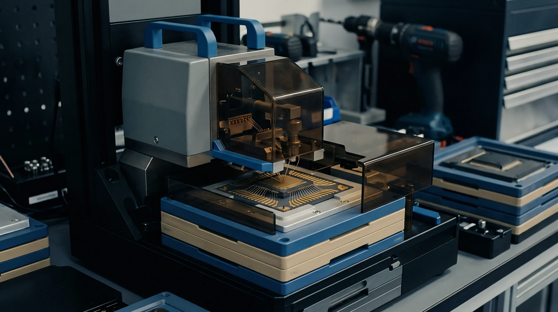
Optical inspection systems typically project structured light or laser lines across the underside of the component to capture the relative height of each pin. This non-contact approach prevents mechanical damage to fragile leads while yielding precise z-axis data. If the deviation exceeds the designated tolerance, often fifty to one hundred micrometres depending on the pitch, the component must be rejected before placement.
Correct calibration of these automated optical inspection units remains mandatory to avoid false negatives during high-speed production runs.
Component Integrity
Inward shipment inspection of integrated circuits frequently uncovers defects introduced during bulk handling or tray transit. Stamping or forming tools at the packaging supplier can also introduce variations that exceed the allowed limit. By identifying defective batches before they enter the assembly line, manufacturers avoid expensive rework and manual touch-up.
Assembly Impact
Solder joint reliability drops significantly when a lead hangs too high above the printed circuit board footprint. This gap prevents the solder from wetting both the pad and the lead, leaving an open circuit or a weak joint that fails during thermal cycling. System qualification demands that these height variations be managed before the reflow oven is reached.