Requalification Protocol Execution for Relocated Multiaxis Measurement Jigs
Requalification of relocated multiaxis measurement jigs mandates thermal soak, 21-parameter laser kinematic mapping, and ISO 10360 volumetric acceptance signoff.


Crate
Precision measurement frames lose structural integrity during transport between manufacturing sites when kinetic impacts, thermal shocks, or stress relaxation take toll on granite basemands. Heavy multi-axis jigs ~ such as bridge coordinate measuring machines and customized articulated inspection frames ~ depend on a static structural balance calibrated in a climate-controlled room. Unbolting a machine from its foundation releases internal stresses previously held by levelling feet and floor anchors.
Transit vibrations alter this force distribution further. Continuous low-frequency input from trucks lacking air-ride suspension loosens mechanical fasteners, settles dampening mounts unevenly, and causes micro-yield shifts across joined aluminum or cast-iron beam junctions.
Rigid transport frames need structural locking mechanisms mounted directly onto linear guideways before moving the machine. Carriages must be pinned mechanically so ballscrews cannot rotate and linear encoder glass scales remain untouched during transit. If left unlocked, free-floating masses strike end-stops, driving impact energy straight into recirculating ball bearings and rail raceways.
Brinelling on these bearing surfaces creates periodic positional errors that show up after relocation as systematic spatial pitch and yaw ripples along affected travel axes.

Structural Isolation and Vibration Dampening Systems
On the floor, heavy optical and mechanical measurement frames rest on active pneumatic isolators or elastomeric mounts. Once pneumatics are bled during decommissioning, the frame settles onto hard transport stops. Shocks exceeding three acceleration units along orthogonal axes alter pre-loaded isolation spring rates.
Monitoring structural settling across relocated gantry jigs identifies transit-induced baseline drift. Standard relocation procedures call for continuous tri-axial acceleration logging attached directly to the bed throughout transit. These loggers record transient impacts during loading, transport, and offloading, giving concrete data to evaluate shock exposure.
Granite slabs retain significant thermal memory long after ambient temperatures change.
Post-relocation stability comes down to foundation design. Anchoring a measurement jig onto concrete floors with variable thickness or inconsistent rebar density twists the base casting. Bolt torque has to follow strict rotational sequences so the granite base does not bend; unequal tightening pulls structural uprights out of true, introducing squareness errors between vertical and horizontal axes.
A floor vibration survey at the destination facility determines whether ambient floor noise stays within original site criteria before machine placement occurs.
Granite structures exposed to unconditioned transit trucks absorb thermal energy that takes up to seventy-two hours to dissipate fully in a temperature-regulated clean room.

Thermal Stabilization and Environmental Soak Protocols
Moving a multi-axis coordinate machine creates thermal gradients across cast-iron bridges and carbon-reinforced columns. Unconditioned transit exposes structural components to ambient temperature spikes and freezing conditions. Because dissimilar metals expand at different rates ~ like steel guide rails bolted to granite beams ~ the structure bows, and that bowing persists until internal temperatures equalize throughout the machine mass.
Environmental soak protocols enforce minimum rest periods before physical alignment can start. A four-metric-ton granite measuring bed needs seventy-two hours inside a temperature-stabilized room holding twenty degrees Celsius within a half-degree tolerance. Calibrating prematurely while heat is still dissipating produces useless compensation matrices; as components expand or contract toward equilibrium, spatial error fields shift and invalidate maps drawn during active temperature movement.
- Bearing Brinelling occurs when sudden shock loads drive recirculating steel balls into linear guide raceways, leaving indentations that show up as localized positioning errors.
- Structural Torsion arises from asymmetric anchor tightening or non-coplanar mounting pads, twisting structural bridges and altering axis squareness.
- Thermal Bowing develops when dissimilar materials undergo rapid temperature shifts, causing differential expansion along structural guide beams.
- Encoder Scale Misalignment results from transport vibration loosening scale mounting clamps, shifting linear grating baselines relative to readheads.
- Pre-Load Relaxation occurs inside mechanical joints when sustained transport oscillation relaxes tension in structural fasteners and kinematic mounts.
Air bearings require clean, dry pressure to prevent surface contact and contamination.
Floor-to-ceiling thermal gradients in the new hall induce localized bending along vertical Z-axis rams. A vertical gradient above one-half degree Celsius per vertical meter tilts vertical guideways. Environmental control units must verify stable air circulation around the machine envelope before mechanical alignment checks begin.
Thermal plumes from nearby machining centers cause dynamic volumetric drift that defeats requalification protocols.
Standard freight tie-down guidelines often fail to protect the micro-yield limits of precision granite isolation pads.

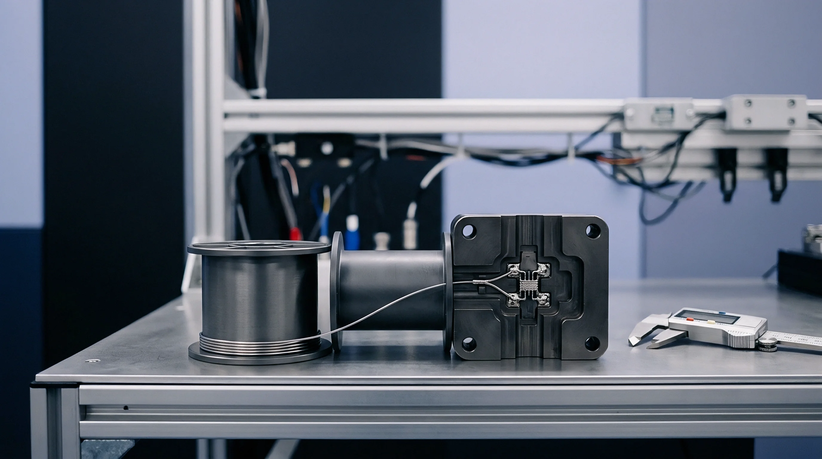
Kinematics
Axis geometric mapping converts physical movement errors into digital compensation matrices across three linear and rotational axes. Multi-axis measurement jigs exhibit twenty-one parametric kinematic errors: three translational displacement errors, three rotational errors, and three perpendicularity squareness errors between orthogonal axes. Relocating a jig disrupts physical alignments, requiring full identification and correction of all twenty-one parametric error components.
Laser interferometers, electronic precision levels, and optical squares isolate individual geometric deviations along each millimeter of axis travel.
Translational positioning error reflects accuracy along the target axis. Linear laser interferometry measures distance deviations between commanded positions and physical carriage positions across specified evaluation intervals. Retroreflector optics mounted on moving carriages bounce split laser beams back to detector heads, measuring phase shifts to resolve positional deviations below ten nanometers.
Environmental sensors tracking ambient temperature, barometric pressure, and humidity update real-time wavelength compensation formulas so atmospheric refraction does not corrupt position data.

Twenty-One Parametric Geometric Errors
Machine tools and coordinate measuring structures experience six degrees of freedom per moving axis, plus perpendicularity offsets between orthogonal guides. Pitch, yaw, and roll represent rotational deviations around the transverse, vertical, and movement axes. Roll errors along long horizontal travel axes create Abbe errors, where angular tilting scales linearly with offset distance from the measurement centerline.
Precision dual-axis electronic levels detect angular pitch and roll deviations down to one-tenth of a arcsecond along granite guide paths.
Squareness errors define angular non-perpendicularity between axis pairs. Evaluating squareness between X and Y axes involves optical squares combined with straightness interferometers or precision pentaprisms. Laser beams aligned along the X-axis reflect through ninety-degree pentaprisms onto the Y-axis guide.
Angular deviations between reflected beams and physical Y-axis paths measure squareness errors directly in micrometers per meter. Torsional base shifts during transport are the primary driver of severe squareness degradation in relocated gantry inspection frames.
| Error Component | Measurement Instrument | Evaluation Standard | Pre-Relocation Limit | Post-Relocation Tolerance |
|---|---|---|---|---|
| Linear Positioning (EXX, EYY, EZZ) | Laser Interferometer | ISO 230-2 | 0.8 µm / m | 1.2 µm / m |
| Straightness (EYX, EZX, EXY, EZY) | Optical Straightedge & Wollaston Optics | ISO 10360-2 | 0.5 µm / m | 0.8 µm / m |
| Angular Pitch & Yaw (EGX, ETX, EGY, ETY) | Dual-Axis Laser Autocollimator | ASME B89.4.19 | 1.0 arcsec | 1.5 arcsec |
| Angular Roll (ERX, ERY, ERZ) | Electronic Precision Differential Level | VDI/VDE 2617 | 1.5 arcsec | 2.0 arcsec |
| Perpendicularity (CXY, CYZ, CZX) | Optical Square & Laser Tracer | ISO 10360-2 | 2.0 µm / m | 2.5 µm / m |
Squareness errors compound significantly along volumetric diagonals.
Rotary table axes on multi-axis measurement jigs demand separate volumetric error mapping protocols. Tilting and rotary stages suffer from radial runout, axial play, and tilt wobble. Relocation shock alters bearing pre-loads on rotary faceplates, causing tilt wobble errors that project volumetric positioning deviations across the inspection envelope.
Angular encoders on rotary axes require calibration using optical polygon mirrors and autocollimators or high-precision rotary index tables. Transporting a rig without proper padding across plant bridges can produce squareness deviations up to 4.2 micrometers per meter along the vertical axis.
A geometric squareness error of three micrometers per meter generates a volumetric diagonal deviation of fourteen micrometers across a two-meter inspection cube.

Laser Interferometer Alignment and Optical Square Evaluation
Precision displacement tracking demands absolute phase alignment between reference beams and retroreflective target mirrors. Commissioning engineers set up optics along machine axes using magnetic bases attached to static structural points. Misalignment between laser beam trajectories and machine motion vectors introduces cosine errors, causing measured distances to underreport physical displacement.
Fine-adjustment mounts alter beam positioning until thermal drift and signal strength indicators stabilize across full travel strokes.
Fasteners and tension bolts lose preload during transport.
Software volumetric compensation builds correction grids stored inside machine controller memory cards. Spatial interpolation algorithms read these lookup tables in real time during inspection routines, applying equal and opposite correction vectors to drive motors. Parametric error maps generated prior to machine relocation must be cleared entirely from controller memory.
Loading legacy error maps into physically altered structures causes controller drives to command incorrect spatial adjustments, compounding mechanical geometric errors.
Replacing damaged laser scale readheads and re-scraping axis guide pads adds twelve thousand dollars in unrecovered labor costs during a secondary alignment phase.


Probe
Sensor assemblies attached to relocated measurement bridges require spatial re-indexation before volumetric inspection begins. Multi-axis measurement jigs deploy tactile touch-trigger probes, continuous scanning heads, or non-contact optical triangulation sensors. Transport subjects delicate probe suspension springs, piezo-electric force transducers, and optical diode paths to mechanical acceleration.
Requalifying probing systems confirms that stylus geometry, triggering threshold forces, and optical sensor spatial offsets match original factory calibration levels.
Stylus tip calibration establishes effective ruby sphere diameters and spatial offset vectors relative to the probe head center. Measuring a reference sphere of known form and diameter yields probe form error values. Contact between stylus tips and calibration spheres must occur at controlled speeds to avoid dynamic impact deflection; approach speeds over ten millimeters per second flex thin carbide shafts, distorting calculated tip radii and underreporting sphere dimensions.

How Does Dynamic Deflection Distort Multi-Probe Volumetric Precision?
Tactile styli experience microscopic bending during high-speed contact routines on complex freeform surfaces. These forces alter vector output coordinates, introducing directional bias into point clouds. Continuous scanning heads drag stylus tips across component surfaces, generating normal and tangential friction forces that deflect long extension rods ~ introducing dynamic probe errors that static single-point calibration routines miss entirely.
Operating with uncalibrated probes invalidates volumetric inspection results.
Dynamic force calibration compensates for stylus bending by recording force-deflection curves across varying approach angles. Advanced scanning probes use internal strain gauges to measure deflection forces directly during contact, feeding bending signals back to controller compensation firmware in real time. Relocation vibrations can disrupt strain gauge bridge balance inside multi-axis probe heads; recalibrating electronic zero-points for force sensors restores uniform sensitivity across all vector directions.
- Stylus Vector Calibration verifies three-dimensional offset coordinates for every tip configuration within an automated indexing probe head assembly.
- Form Error Evaluation measures shape deviations when probing a certified grade-one reference sphere across uniformly distributed contact points.
- Dynamic Deflection Mapping quantifies stylus shaft bending forces encountered during high-speed surface contact scanning routines.
- Optical Sensor Offset Calibration determines exact spatial location parameters for non-contact laser lines relative to the physical machine quill center.
- Triggering Repeatability Validation calculates three-sigma positional dispersion across twenty successive touch points executed on a static reference standard.
Uncorrected stylus deflection directly distorts contact measurement data.
Non-contact optical line scanners and laser triangulation sensors require separate requalification workflows following machine relocation. Transport shock shifts internal optical bench alignment within sensor housings, altering laser diode projection angles relative to internal complementary metal-oxide-semiconductor detector arrays. Optical sensor calibration uses certified planar targets or sphere artifacts to map laser line linearity, depth-of-field resolution, and spatial stand-off distance.
Ambient lighting and thermal emissions from nearby shop equipment alter detector noise levels, requiring background illumination cancellation during site setup.
Evaluating stylus tip deflection vectors across five distinct approach angles verifies automated tool-changer offsets.
Whether non-contact laser line sensors can maintain sub-micron spatial offsets under fluctuating air currents remains an open operational question for high-speed scanning installations.


Verification
Standardized length measurements establish final acceptance baselines for multi-axis measuring machinery following site transfer. International standards ISO 10360-2 and ASME B89.4.22 define volumetric measurement protocols designed to stress machine kinematics along space diagonals and parallel axis lines. Requalification mandates recording volumetric length measurement errors across five material standards of length placed within the machine working volume, using test artifacts like calibrated step gauges, laser tracer systems, or end standards made from low-expansion materials such as Zerodur or Invar.
Evaluating length measurement error requires taking five distinct lengths per line location, repeated three times per orientation ~ yielding one hundred five total measurement points across seven defined volumetric paths. Volumetric diagonal measurements evaluate compound kinematic errors by moving X, Y, and Z axes simultaneously. If measured length errors exceed maximum permissible error boundaries, the machine fails site acceptance.
Re-analyzing parametric error tables isolates which geometric axis component caused the out-of-tolerance condition.

Volumetric Precision under ISO 10360 Standards
Step gauges, calibrated titanium gauge blocks, and laser tracer arrays evaluate maximum permissible error across volumetric diagonals. International specification ISO 10360-2 defines length measurement performance through mathematical expressions combining baseline constant error terms with length-dependent scale factors. A typical performance claim expresses maximum permissible error as one point five plus L over three hundred micrometers, where L is the measured length in millimeters.
Relocation protocols require verifying performance across short, medium, and maximum travel lengths to confirm linear scale interpolation integrity.
Thermal gradients shift internal machine baselines.
Tactile probing performance verification under ISO 10360-5 evaluates probing form error and probing size error using twenty-five points distributed across a certified spherical artifact. Probing form error is the range of radial distances containing all twenty-five points; probing size error is the delta between calculated sphere diameter and certified diameter. Relocation stress that degrades probe head kinematics shows up as elevated probing form error values before length measurement errors fall outside specification limits.
| Test Parameter | Artifact Type | Evaluation Envelope | Pass/Fail Threshold (MPE) | Statistical Confidence |
|---|---|---|---|---|
| Length Error (E0, MPE) | Calibrated Step Gauge | Parallel to Axes (X, Y, Z) | 1.2 + L / 350 µm | 95% Confidence Limit |
| Diagonal Error (ED, MPE) | Laser Tracer System | 3D Volume Diagonals | 1.5 + L / 300 µm | 95% Confidence Limit |
| Probing Form (PFTU) | Grade 5 Ruby Sphere | Central Working Volume | 1.0 µm Maximum Range | Single Probe Tip (25 Pts) |
| Probing Size (PSTU) | Grade 5 Ruby Sphere | Central Working Volume | ± 0.8 µm Diameter Delta | Single Probe Tip (25 Pts) |
| Repeat Precision (R0) | End Standard / Gauge Block | Fixed Location (10 Runs) | 0.4 µm Maximum Spread | 3-Sigma Standard Dev |
Laser tracer systems resolve spatial vector errors across three dimensions.
Measurement system analysis protocols evaluate repeatability and reproducibility under operational conditions after mechanical re-calibration. Type 1 gauge studies record fifty consecutive measurements on a single reference standard to calculate capability metrics, including potential capability index and real capability index. Values exceeding one point three three demonstrate acceptable measurement system capability relative to part tolerances.
Low capability ratios signal lingering mechanical hysteresis, thermal instability in the environment, or worn drive components from handling during relocation.
Compliance with ISO 10360-2 clause 6.2 forces immediate recalibration whenever length measurement error exceeds maximum permissible error limits during site validation.

Site Acceptance Execution Sequence
Commissioning engineers initiate physical re-certification only after ambient room conditions settle within designated thermal bands.
- Environmental verification logs ambient room temperature, spatial thermal gradients, and floor vibration spectrums over a continuous twenty-four hour baseline period.
- Physical mechanical inspection checks structural torque values, pneumatic supply pressures, and air bearing gap clearances across all travel axes.
- Controller memory purge removes legacy volumetric compensation tables and clears historical home position offset parameters.
- Parametric laser alignment maps linear positioning, pitch, yaw, roll, and perpendicularity squareness across every axis movement range.
- Software compensation generation compiles newly acquired kinematic data into updated spatial correction matrices and uploads them to controller firmware.
- Probing system calibration indexes stylus tip offset vectors, calculates tip radii, and verifies force sensor triggering repeatability.
- Standardized ISO 10360 volumetric acceptance testing executes length and diagonal measurements to validate final machine accuracy.
- Gauge repeatability and reproducibility studies confirm operational measurement capability on actual production artifacts prior to production release.
Inadequate settling times distort test outcomes.
Uncalibrated linear scales report inaccurate position values.
Incorporating ISO 10360-5 Annex B into the acceptance protocol obligates the vendor to re-test tactile probing error at forty-five distinct vector angles before signoff.

Acceptance
Formal signoff transfers operational risk from the relocation contractor to the plant quality manager. Completing physical calibration without structured administrative verification leaves manufacturing sites exposed to unassigned financial liabilities when measurement discrepancies show up during production runs. Relocation contracts need clear boundaries between logistics responsibilities, OEM technical commissioning scopes, and site acceptance criteria.
Detailed acceptance dossiers consolidate sensor calibration certificates, raw laser interferometer data files, and ISO 10360 test reports into permanent machine history files.
Factory Acceptance Testing executed before machine dismantling establishes baseline capability limits. Comparing post-relocation Site Acceptance Testing metrics against original pre-move data isolates transport damage from pre-existing mechanical wear. If post-relocation squareness errors exceed pre-move baselines while staying within published OEM thresholds, assigning responsibility hinges on contractual scope language ~ specifically, whether contractors must restore original performance levels or merely meet baseline catalog specs.

Factory Acceptance Metric Transfer to Site Testing
Baseline calibration metrics established before machine teardown serve as contractual benchmarks for post-transit validation. Pre-move data documents initial volumetric accuracy, probing form error, and axis straightness profiles. Transport contractors sign off on pre-move inspection reports to confirm machine status before teardown starts.
Discrepancies between pre-move baseline records and site acceptance results isolate physical damage or structural settling that occurred during transit.
Pneumatic dampeners help absorb floor-borne shock and vibration.
Structuring relocation scopes of work ensures site acceptance signoff binds both logistics vendors and metrology integrators.
| Relocation Activity | Responsible Party | Verification Requirement | Commercial Liability Exposure |
|---|---|---|---|
| Teardown & Axis Pinning | OEM / Certified Specialist | Mechanical Lock Signoff Sheet | Component Damage from Improper Locking |
| Transit Shock Management | Logistics Freight Provider | Tri-Axial Shock Logger Report | Transport Damage Exceeding 3g Impact |
| Foundation Preparation | Destination Facility Manager | Floor Anchor & Vibration Survey | Structural Torsion from Substrate Flexing |
| Kinematic Re-Alignment | Metrology Calibration Vendor | Laser Interferometry Raw Logs | Uncorrected Geometric Axial Errors |
| Final ISO Re-Certification | Joint Scope Signoff Team | ISO 10360-2 Certificate Dossier | Production Downtime & Scrap Part Costs |
Transit shocks cause structural shifting across machine frames.
Non-recurring engineering expenses listed in relocation quotes often conceal exclusions regarding software compensation map generation. Low-cost quotes may cover mechanical re-erection while omitting twenty-one parameter volumetric compensation mapping. Unbundling alignment services leaves site managers forced to buy separate calibration packages to fix post-move volumetric errors.
Sourcing contracts should mandate turnkey engineering scopes covering all teardown, transport, re-alignment, software compensation, and ISO certification steps under a unified fixed price schedule.
Operational custody of a relocated metrology rig passes to the buyer only after physical re-certification metrics mirror pre-move baseline records.

Commercial Responsibility and Re-Certification Scope
Contractual agreements define whether recalibration costs after transit damage fall on logistics providers or equipment OEMs. Insurance claims covering transit impacts require immediate submission of physical shock logger records alongside laser interferometer scans showing structural deformation. Without baseline pre-move data, underwriters frequently argue that geometric alignment errors stemmed from long-term wear rather than transit shock events.
Uncorrected volumetric drift requires complete spatial remapping.
- Pre-Move Baseline Record captures certified kinematic, optical, and volumetric performance data prior to machine mechanical dismantling.
- Transport Log Attestation provides continuous tri-axial acceleration and environmental temperature records logged during freight transit.
- Laser Alignment Raw Logs contains unedited digital data files generated by interferometers and autocollimators during site re-calibration.
- Updated Controller Backup archives newly generated volumetric compensation lookup tables and axis offset settings in secure digital storage.
- ISO Acceptance Certificate validates that machine volumetric accuracy satisfies ISO 10360-2 and ASME B89 limits under post-relocation site testing.
Formal contract signoffs establish final operational liability.
Engineering scope boundaries hold firm only when signoff milestones link final payment release directly to verified volumetric repeatability.