Isolating Undocumented Silicon Errata during Microcontroller Design Transfers
Isolating undocumented silicon errata requires bare-metal assembly isolation routines, stepping identification, and precise SOW change-control terms.


Discrepancy
Moving a microcontroller design from a vendor demonstration board to a contract assembly line causes dropped bus arbitration frames whenever the direct memory access controller completes a burst transaction during sleep transitions. While the early engineering prototype ran without issue on the vendor evaluation board, populating the identical part number onto a high-density target board triggers intermittent serial communication failures under load. The laboratory prototype used early silicon engineering samples, whereas the volume manufacturing line receives commercial production steppings with altered internal timing margins.

Signal Integrity Variance between Boards
Subtle shifts in PCB trace impedance can modify edge rise times enough to cause setup-and-hold violations in peripheral flip-flops. Vendor evaluation boards route signals across spacious four-layer microstrip layouts planned specifically to maximize operating margins during lab bench demonstrations. Target production assemblies compress those interconnects into six-layer blind-via stackups that introduce higher parasitic capacitance and mutual coupling.
That layout difference alters clock slew rates at the chip pins; when an internal peripheral domain synchronizes with an external crystal oscillator, power rail ripple easily tips internal flip-flops into metastable states.

Vendor Abstraction Drivers Mask Chip Defects
Factory software development kits routinely embed undocumented register writes inside initialization routines to bypass known silicon bugs. Software teams writing bare-metal drivers or bringing up a lightweight real-time operating system often bypass these vendor routines, leaving the peripheral in an uncalibrated hardware state. Silicon vendors regularly update their driver packages with hidden workarounds without publishing corresponding errata notices in datasheet revisions.
Replacing the vendor HAL with an optimized custom driver during design transfer drops that unmasked silicon defect directly into production firmware builds.
| Parameter | Vendor Evaluation Board | Target Assembly Line | Failure Mechanism |
|---|---|---|---|
| Power Rail Ripple | 12 mV peak-to-peak | 48 mV peak-to-peak | Internal Phase-Locked Loop Jitter |
| Trace Capacitance | 8 pF per inch | 18 pF per inch | GPIO Edge Slew Rate Degradation |
| Driver Layer | Vendor Binary SDK v2.4 | Custom Bare-Metal HAL | Omitted Undocumented Register Patch |
| Silicon Stepping | Revision A (Engineering Sample) | Revision B (Commercial Volume) | Modified Internal Bus Matrix Priority |
Contract electronics manufacturers transfer engineering risk to component buyers when design documentation lacks low-level register initialization sequences.
Customer layout parasitics routinely fall outside published reference design guidelines.


Mask
Silicon manufacturers frequently update internal stepping revisions without altering the catalog marketing part number. A microcontroller procured under one ordering code across two consecutive years can easily contain different physical masks. Fabs shrink transistor gate lengths, optimize die area, or reroute upper metal interconnects to increase wafer yield.
Those physical adjustments alter internal peripheral timing, bus hold windows, and analog comparator offsets.

Stepping Revision Records and CPUID Registers
Silicon die revisions store explicit revision markers within dedicated identification registers accessible through debug interfaces. Inspecting the silicon revision identifier register reveals whether incoming production lots match the silicon qualified during prototyping. Specific bits across the CPUID register or System Control Block indicate these die stepping variants.
When contract manufacturers source microcontrollers through broker channels, mixed silicon steppings can end up packaged on the same tape and reel. Firmware written and tested on Revision A silicon will hang on Revision B if internal bus matrix arbitration timing shifted between mask revisions.

Foundry Process Node Shifts
Transferring die production from an original fabrication line to a second-source foundry alters transistor threshold voltages. A microcontroller ported from a 90-nanometer planar process down to a 65-nanometer geometry exhibits faster logic gate switching speeds. These sharper edges draw heavier transient currents during simultaneous peripheral switching events.
The resulting current surges induce localized voltage drops across internal power rails, destabilizing instruction execution inside the core processing unit.
A standard silicon vendor supply contract excludes unlisted register state corruptions from warranty claims unless reproduced on official evaluation boards.
The operational mechanisms causing unannounced silicon behavior shifts during design transfers include:
- Internal Bus Matrix Timing Tweaks shift interrupt latencies by two core clock cycles, breaking microsecond-level timing loops in custom motor control algorithms.
- Analog Comparator Offset Drifts alter low-voltage detect threshold triggers, causing unexpected system resets during heavy radio transmission bursts.
- Flash Memory Prefetch Buffer Revisions introduce wait-state insertion bugs when executing branch instructions near sector boundaries.
- Internal Resistance Shifts change GPIO drive strength output impedance, causing peripheral bus line ring reflections on production PCBs.
New silicon mask revisions resolve documented peripheral defects while silently altering undocumented clock tree propagation delays.
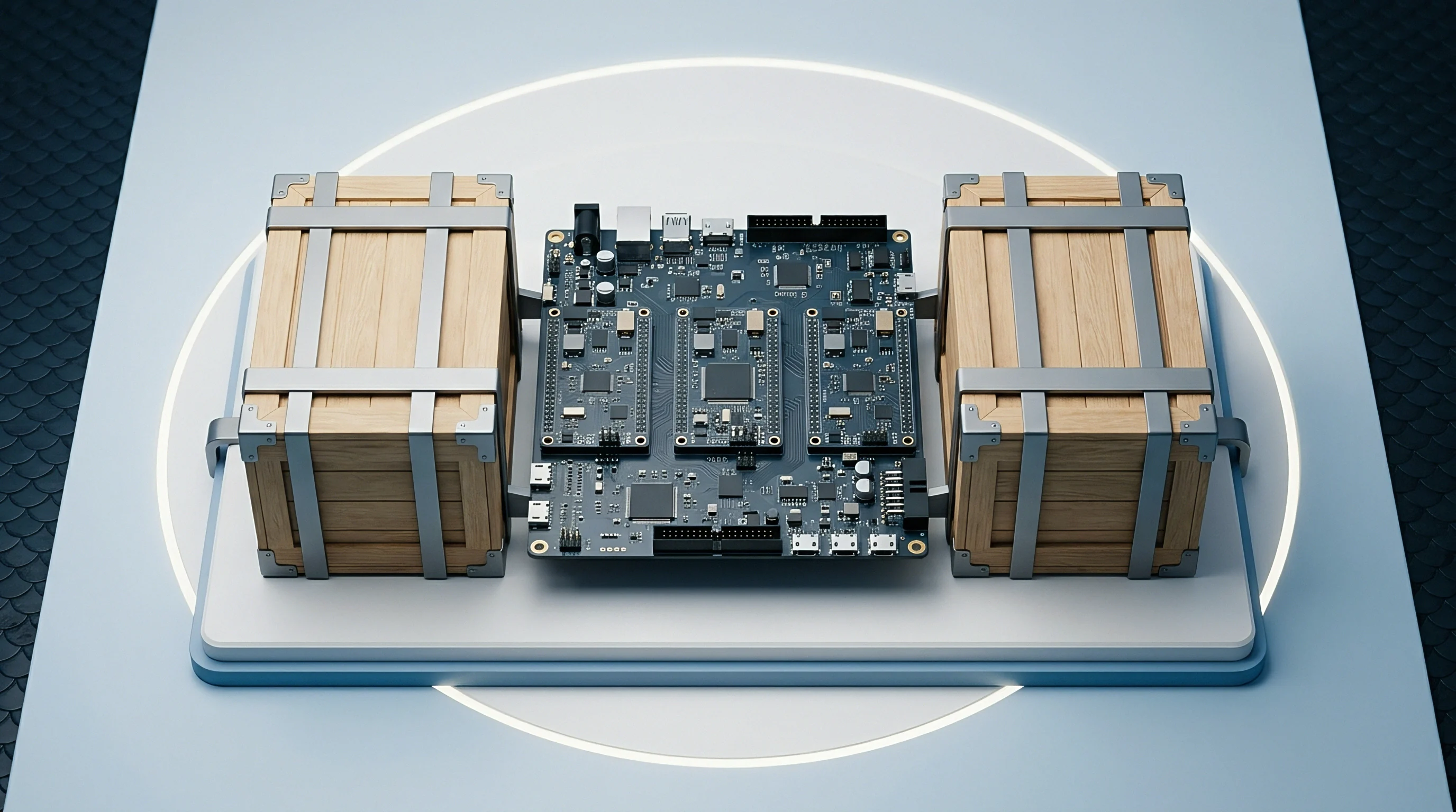

Triage
Isolating a silicon erratum requires stripping away peripheral drivers and operating system schedulers until only raw machine code remains. When a microcontroller design transfer misbehaves on the manufacturing floor, separating software flaws from solder defects and silicon bugs requires methodical isolation. Diagnostics start by reproducing the failure inside a deterministic test loop, holding supply voltages, ambient temperature, core clock speeds, and bus traffic under strict control.

Bare-Metal Assembly Isolation Sequences
Executing hand-crafted machine code directly out of instruction RAM bypasses pipeline hazards caused by flash prefetch buffers. The diagnostic harness turns off all interrupts, runs core clocks from internal relaxation oscillators, and initializes target peripherals in their simplest operational modes. By bypassing vendor abstraction libraries entirely, the test routine executes minimal assembly instructions directed straight at the failing peripheral register.
If the peripheral still locks under these deterministic conditions, the failure resides in the silicon die or pin electrical interface rather than the application software stack.

Worked Case of DMA Bus Matrix Deadlock
A 32-bit microcontroller system freezes during simultaneous Ethernet reception and flash erase cycles. On a production target board failing at a four percent rate during factory end-of-line testing, the system clock runs at 120 MHz, with the Direct Memory Access controller transferring packets into internal SRAM while the flash controller executes a 256-byte page write operation.
Under baseline conditions, the failure rate scales with core clock frequency. Dropping the clock from 120 MHz to 60 MHz cuts the failure rate by eighty percent without resolving the underlying lockup. The isolation sequence proceeds step by step:
- Connect a logic analyzer to internal bus matrix debug pins and trace SRAM arbitration request signals.
- Replace application software with a 40-byte assembly routine that triggers DMA transfers and flash page writes inside an infinite loop.
- Monitor the Bus Matrix Arbitration State Register via an embedded trace buffer during transaction freezes.
- Observe that the SRAM controller locks into a permanent wait-state when DMA Channel 2 and the Flash Controller request SRAM access on the exact same core clock cycle.
- Apply a controlled core voltage reduction from 3.3 V to 3.0 V to increase internal propagation delay, which expands the failure window to a 100 percent lockup state.
The test confirms an undocumented silicon bus arbitration deadlock where dual simultaneous master requests cause internal state machine stall conditions inside the bus matrix controller.
| Domain | Observed Symptom | Isolation Instrument | Diagnostic Output |
|---|---|---|---|
| Bus Matrix | Core CPU execution lockup | Embedded Trace Macrocell | Permanent SRAM wait-state signal high |
| Power Rails | Spurious Brown-Out Reset | 1 GHz Oscilloscope with Active Probe | 180 mV dip on VDDCORE during DMA burst |
| Clock Tree | UART framing errors at high temperature | Frequency Counter and Thermal Chamber | Baud rate clock drift exceeding 3.5 percent |
| Flash Controller | Instruction read corruption | Boundary Scan JTAG Test Bench | Prefetch buffer cache line parity mismatch |
Bare-metal assembly drivers expose silicon design bugs that high-level abstraction libraries hide beneath software retry loops.
Which register states remain unrecorded when internal bus arbitration deadlocks halt the debug trace clock during instruction fetch operations?


Workaround
Remediating undocumented hardware bugs requires choosing between firmware register patches and physical circuit board modifications. Once isolation confirms an erratum, engineering must implement a durable workaround to recover line yields. Software workarounds adjust peripheral timing, resequence register initialization steps, or implement resource lockouts, whereas hardware changes modify schematics, add filtering components, or tie pins to stable logic levels.

Software Patching Strategies
Interrupt service routines can clear undocumented race conditions by executing dummy memory barrier cycles prior to peripheral flag resets. Driver architectures can be restructured to prevent the simultaneous bus transactions that trigger internal lockups. Inserting NOP assembly instructions between consecutive register writes allows internal peripheral pipeline logic to settle before processing subsequent commands.
Software patches incur slight processing overheads but eliminate costly circuit board layout respins during active production runs.

Hardware Board Modifying Steps
Adding external pull-up resistors or ferrite beads suppresses ground bounce that triggers phantom interrupt request lines. When internal silicon pull-ups develop undocumented leakage across wider temperature ranges, board revisions replace them with external precision resistors. Factory bring-up teams follow an established sequence when implementing hardware remedies during design transfer qualification:
- Identify affected silicon pins using high-speed active logic probes under worst-case operating temperatures.
- Isolate external board traces from adjacent high-frequency signal switching paths using ground shielding lines.
- Solder external bypass capacitors directly across localized power supply pins to absorb current surges.
- Update manufacturing assembly drawings and bill of materials documentation to reflect modified component values.
A four-nanosecond core clock glitch under low-power stop mode forces a hardware reset when ambient temperature exceeds eighty-five degrees Celsius.
Unresolved silicon errata left unpatched in target production builds lead to random field failures, continuous line yield loss, and expensive customer product recalls.


Arbitration
Commercial scope agreements govern who absorbs the financial exposure of unmapped silicon defect remediations during factory handovers. Design transfer packages define ownership of the engineering hours required to troubleshoot unexpected microcontroller behavior. When transfers shift manufacturing from an in-house facility to a contract manufacturer, ambiguous statements of work trigger financial disputes over pre-production scrap costs and engineering rework hours.

Statement of Work Deliverables
Engineering transfers require formal acceptance tests verifying chip behavior across temperature extremes. Transfer documentation specifies exact software HAL driver versions, board stackup tolerances, and silicon stepping revision constraints. A complete transfer package includes verified bare-metal diagnostic software routines designed to validate incoming silicon lots prior to surface-mount assembly.

Cost Distribution Models
Non-recurring engineering quotes split diagnosis hours from manufacturing scrap expenses during pre-production qualification. Turnkey contracts hold the manufacturing vendor responsible for yields above agreed thresholds, provided components match exact approved bill of materials specifications. Design transfer contracts determine how silicon defect costs map across project parameters:
- Turnkey Engineering Scope assigns responsibility for component yield and bring-up debugging to the contract manufacturer under fixed unit pricing.
- Semi-Custom Transfer Scope splits engineering costs, requiring the buyer to cover silicon errata root-cause diagnosis while the factory absorbs scrap assembly costs.
- Reference Design Transfer Scope places complete technical exposure on the buyer when adapting vendor evaluation schematics to target layouts.
- White-Label Manufacturing Scope restricts vendor liability exclusively to board solder joint quality and passive component assembly accuracy.
| Integration Level | Errata Isolation Labor | Firmware Patch Cost | PCB Respin Expense | Scrap Assembly Exposure |
|---|---|---|---|---|
| Turnkey Module | Contract Manufacturer | Contract Manufacturer | Contract Manufacturer | Contract Manufacturer |
| Semi-Custom Assembly | Shared Engineering | Buyer Engineering | Buyer Engineering | Contract Manufacturer |
| Reference Transfer | Buyer Engineering | Buyer Engineering | Buyer Engineering | Buyer Engineering |
| White-Label Build | Buyer Engineering | Buyer Engineering | Buyer Engineering | Buyer Engineering |
An IPC-1752A material declaration clause combined with a formal Engineering Change Order agreement mandates that contract manufacturers obtain written buyer approval before populating alternate silicon stepping revisions on production lines.