Evaluating Hybrid Layer Capacitor Buffer Sizing under Repeated RF Transmit Dips
Buffer sizing under repeated RF bursts requires combining peak ESR drop with repetition airtime energy integration at minimum operating temperature.

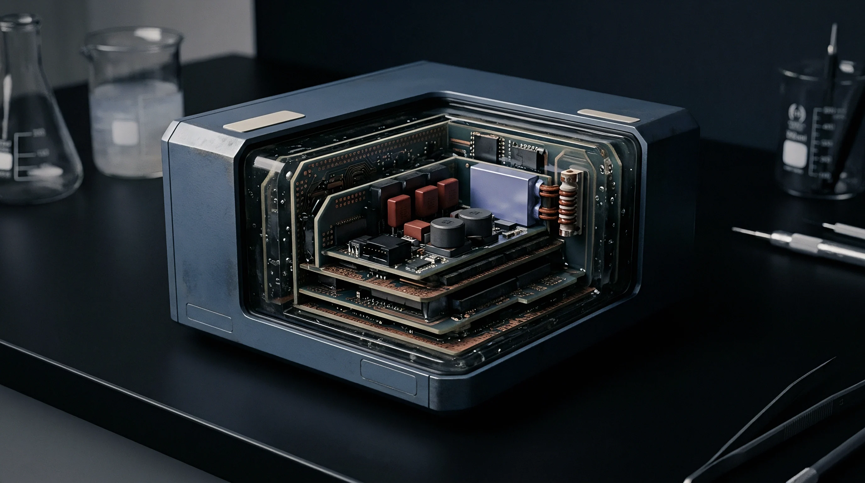
Sag
Transceiver current spikes during cellular or sub-gigahertz LPWAN transmission expose the fundamental limitation of primary lithium cells. A lithium thionyl chloride bobbin cell delivers energy density exceeding 650 watt-hours per kilogram, yet internal impedance restricts sustained discharge to tens of milliamperes. Connecting a transceiver that demands two amperes during a power amplifier pulse causes an immediate terminal voltage collapse below the operating cutoff.
The hybrid layer capacitor functions as a low-impedance charge reservoir across the cell terminals, supplying peak burst currents while the primary chemistry restores depleted charge between packets.
Transient voltage drop across the supply rail consists of three distinct electrical components occurring in series. Ohmic drop appears instantaneously across the equivalent series resistance of the capacitor and printed circuit board traces. Capacitive discharge produces a continuous downward slope across the duration of the radio burst as stored energy transfers into the power amplifier.
Electrochemical recovery lags behind the RF event, bounded by the diffusion rate of the primary battery and the series resistance of the cell-capacitor junction.
Baseband resets follow immediately.
When wireless nodes operate at the edge of cell coverage, link degradation forces modulation changes and packet retransmissions. 3GPP standards define maximum transmit power levels of 23 dBm for LTE-M and NB-IoT devices, generating baseband and amplifier current spikes between 300 mA and 600 mA. GSM transmissions reach two amperes during burst phases.
If repetitive transmission cycles occur before the primary cell replenishes the hybrid layer capacitor, the operational voltage rail steps down incrementally until triggering brownout detectors.
Catastrophic supply line failure modes emerge through predictable operational triggers:
- Instantaneous brownout tripping occurs when equivalent series resistance causes terminal voltage to breach the minimum baseband supply limit within microseconds of power amplifier activation.
- Cumulative charge depletion develops across closely spaced packet bursts when inter-burst idle windows prevent complete capacitor potential restoration.
- Passivation breakdown latency leaves the primary cell unable to deliver recharge current after extended sleep periods, shifting the entire energy demand onto the buffer.
- Thermal rail contraction narrows the margin between nominal cell potential and operating cutoff at sub-zero temperatures through simultaneous resistance elevation and active capacity reduction.
Subsystem failure from unmitigated bus collapse extends beyond lost packets. Repeated low-voltage interruptions corrupt flash memory sectors during non-volatile write routines, destabilize real-time clock calibration, and lock cellular baseband processors into unrecoverable loop states that exhaust battery capacity within days.

Electrochemical Interface Dynamics
Primary lithium thionyl chloride cells form a lithium chloride crystal layer over the lithium anode during storage and quiescent listening intervals. This passivation film protects the anode from self-discharge, yielding shelf lives exceeding fifteen years at room temperature. The protective film functions as a series resistor that restricts current flow during initial load application.
A bare cell subjected to an unscheduled radio transmit pulse experiences a delay of milliseconds to seconds before the film breaks down and allows potential to recover.
Hybrid layer capacitors resolve this delay through parallel integration. Fabricated with lithium intercalation anodes and electric double-layer cathode structures, these components store charge through both electrostatic adsorption and fast faradaic surface reactions. Nominal cell potential sits between 3.6 V and 3.9 V, aligning with the operating voltage plateau of bobbin lithium thionyl chloride cells without requiring active voltage regulators or series protection diodes.
The module shuts down.
Temperature shifts alter internal transport kinetics across both storage elements. As temperature falls toward minus 40 degrees Celsius, electrolyte viscosity rises and ion migration rates decline. Equivalent series resistance in the hybrid layer capacitor escalates by a factor of five to ten, while primary cell internal resistance climbs by more than an order of magnitude.
The usable capacitance of the hybrid device drops by 20 to 40 percent under cold conditions.
A standard 1520-size hybrid layer capacitor exhibits an equivalent series resistance climb from 120 milliohms at 20 degrees Celsius to 850 milliohms at minus 40 degrees Celsius.
The following dataset compiles measured electrical characteristics across commercial hybrid layer capacitor form factors evaluated across operating temperature boundaries.
| Device Form Factor | Nominal Capacitance (F) | ESR at 20C (mΩ) | ESR at -40C (mΩ) | Max Continuous Current (mA) | Max Pulse Current (A) |
|---|---|---|---|---|---|
| HLC 1020 | 25 | 350 | 1850 | 250 | 1.0 |
| HLC 1425 | 50 | 200 | 1200 | 500 | 2.0 |
| HLC 1520 | 100 | 120 | 850 | 750 | 3.0 |
| HLC 1530 | 140 | 100 | 680 | 1000 | 4.0 |
| HLC 1550 | 350 | 55 | 380 | 2000 | 5.0 |
Component vendors routinely dismiss low-temperature brownouts as anomalous transient excursions caused by improper customer PCB layout rather than electrochemical kinetics.

Radio Protocol Bursts and Repetitions
Wireless physical layers dictate the cadence, magnitude, and persistence of current dips. In basic point-to-point sub-gigahertz transceivers, transmission consists of isolated frames lasting between 10 ms and 50 ms at current draws near 100 mA. Cellular standards enforce demanding current profiles characterized by rapid modulation shifts and protocol-mandated retries.
Under 3GPP Coverage Enhancement Level 2, an NB-IoT transceiver operating in extreme coupling loss conditions repeats each uplink transport block up to 128 times to accumulate decoding energy at the base station.
Coupling losses force repetitions.
The link collapses.
Repetition bursts occur in discrete subframes separated by narrow guard intervals. In single-tone NB-IoT transmissions with 3.75 kHz subcarrier spacing, an uplink slot spans 2 ms. When the protocol schedules contiguous subframes, the buffer capacitor sustains a semi-continuous discharge lasting several seconds.
The primary battery cannot deliver meaningful charge during this rapid sequence because internal resistance limits cell delivery to a fraction of the demand.
Repeated transmission bursts without sufficient electrochemical recovery transform transient voltage dips into permanent module resets.
Energy budgets across major LPWAN and cellular standards show stark divergence in pulse duration and buffer requirements:
| Protocol and Profile | Transmit Power (dBm) | Peak Current (mA) | Burst Duration (ms) | Repetition Count | Total Airtime Energy (J) |
|---|---|---|---|---|---|
| LoRaWAN EU868 DR0 | +14 | 45 | 1318 | 1 | 0.21 |
| LoRaWAN US915 DR0 | +20 | 120 | 370 | 1 | 0.16 |
| LTE-M Cat-M1 23dBm | +23 | 420 | 10 | 16 | 0.24 |
| NB-IoT Rel 13 Single-Tone | +23 | 280 | 32 | 32 | 1.03 |
| NB-IoT Rel 14 Multi-Tone | +23 | 540 | 8 | 64 | 1.24 |
| NB-IoT ECL2 Repetition Max | +23 | 280 | 256 | 128 | 32.90 |
Packets fail silently.
Selecting the appropriate capacitor volume demands precise boundary constraints derived from worst-case protocol airtime:
- Maximum repetition depth sets the total continuous active discharge period during worst-case path loss conditions.
- Minimum inter-burst spacing establishes the available electrochemical recharge window between successive transmission frames.
- Protocol handshake constraints enforce strict timing windows wherein buffer collapse aborts network reattachment attempts.
- Transmit power escalation shifts pulse amplitude dynamically based on carrier network open-loop power control commands.
Power amplifier efficiency drops at supply voltages below 3.3 V, compelling DC-DC boost converters or baseband supply rails to pull higher current to maintain radiated RF power. A diminishing supply rail accelerates charge depletion through an escalating current feedback cycle.
Mathematical Modeling of Dynamic Buffers
Analytical dimensioning begins by establishing the minimum allowable bus voltage during active transmission. The lower voltage boundary equals the highest threshold among the module shutoff voltage, the flash write limit, and the linear dropout floor. A 3.6 V nominal primary cell working into a radio module with a 2.85 V cutoff leaves an absolute permissible voltage drop of 750 mV.
This headroom must absorb both ohmic losses across the capacitor equivalent series resistance and bulk capacitive discharge across the repetition burst train.
Recharge currents taper exponentially.
The total voltage drop across a continuous burst sequence follows the direct expression where total sag equals peak current multiplied by capacitor equivalent series resistance, plus active current multiplied by pulse duration divided by effective capacitance. When the primary cell provides partial recharging current through internal resistance R_cell, the effective recharge rate governs recovery between subframes. The net charge balance across an n-burst repetition sequence dictates capacitor sizing through the equation:
C_min = (I_tx t_pulse n – I_recharge t_gap (n – 1)) / (V_initial – V_cutoff – I_tx ESR)
Consider an NB-IoT water meter operating at minus 20 degrees Celsius. The transceiver transmits at 23 dBm, consuming 320 mA for 128 continuous repetitions of 4 ms bursts separated by 1 ms gaps. Total active duration equals 512 ms.
The primary cell presents a passivated internal resistance of 150 ohms at cold temperature, holding open-circuit potential at 3.5 V. Minimum transceiver operating voltage is 2.85 V. At minus 20 degrees Celsius, an HLC 1520 exhibits an ESR of 350 mΩ.
Ohmic drop across capacitor resistance consumes 112 mV immediately upon burst assertion (320 mA 0.35 Ω). Usable capacitive potential drop narrows to 538 mV (3.5 V – 2.85 V – 0.112 V). During the 1 ms inter-burst gap, the primary cell supplies recharge current capped by its 150 ohm internal impedance, delivering approximately 4.3 mA.
Net discharged energy over the sequence demands a minimum active capacitance of 28.4 farads. Selecting a 25 farad buffer results in bus brownout on burst 114.
Specifying a 3GPP coverage enhancement level without budgeting for maximum radio repetitions invalidates the primary battery operating warranty.
The calculation below maps required buffer capacitance against temperature and coverage levels for NB-IoT deployments.
| Operating Temperature (C) | Coverage Level | Total Airtime (ms) | Assumed ESR (mΩ) | Calculated C_min (F) | Selected Component |
|---|---|---|---|---|---|
| +20 | Normal (ECL0) | 16 | 120 | 1.8 | HLC 1020 (25F) |
| +20 | Enhanced (ECL1) | 128 | 120 | 14.2 | HLC 1020 (25F) |
| +20 | Extreme (ECL2) | 512 | 120 | 56.8 | HLC 1520 (100F) |
| -20 | Normal (ECL0) | 16 | 350 | 3.1 | HLC 1020 (25F) |
| -20 | Enhanced (ECL1) | 128 | 350 | 24.6 | HLC 1425 (50F) |
| -20 | Extreme (ECL2) | 512 | 350 | 98.4 | HLC 1530 (140F) |
| -40 | Extreme (ECL2) | 512 | 850 | 184.2 | HLC 1550 (350F) |
Master supply agreements stipulate that battery life guarantees become void if application firmware commands repetition depths exceeding the maximum current profiles documented in agreed source control drawings.

Empirical Stress Characterization
Simulating capacitor depletion curves on a computer spreadsheet fails to replicate the coupled electro-thermal decay that occurs inside an environmental test chamber. Validating pulse buffer reliability requires physical instrumentation that synchronizes RF protocol state logging with high-bandwidth power rail measurements. A current shunt resistor placed between the primary cell and the capacitor bank captures recovery currents, while differential probes on the transceiver supply pins measure true transient dips.
Margins vanish in minutes.
Executing stress screening requires an uncompromising physical procedure:
- Mount the integrated cell and capacitor assembly inside a calibrated climate chamber soaked at minus 40 degrees Celsius for twenty-four hours to induce full electrolyte stabilization.
- Connect the radio module to a base station emulator configured to command maximum link coupling loss and force the highest protocol repetition index.
- Trigger a continuous cold-start reattachment sequence simulating an unannounced cell tower handover.
- Capture supply rail voltage transients using an oscilloscope sampling at a minimum of one megasample per second to catch sub-microsecond ohmic drop edges.
- Monitor baseband serial logs concurrently to verify whether brownout warning flags trip in firmware registers.
- Subject the primary battery to an accelerated passivation cycle between multi-burst sessions to verify buffer behavior under peak anode film resistance.
Cold slows electrochemical kinetics.
Bench tests conducted at room temperature fail to expose capacitor buffer starvation during cold field deployments.
The cell starves.
A curious operational discrepancy persists regarding the exact aging mechanisms of hybrid layer capacitors after fifteen years of continuous trickle charging in sub-surface utility pits. Field extraction data remains thin, leaving hardware architects divided over whether electrolyte dry-out or interface micro-cracking will dominate wear-out curves as deployed LPWAN water meters enter their second decade of operation.