Primary Cell Voltage Response during Multi-Second Cellular Repetition Bursts
Continuous multi-second cellular repetition bursts pull battery voltage below brownout limits unless buffered by low-ESR capacitors.

Passivation
During storage, a crystalline lithium chloride film forms spontaneously on metallic lithium anodes inside primary liquid-cathode cells. While this non-conductive layer prevents self-discharge and stretches shelf life up to twenty years in lithium thionyl chloride chemistries, it also introduces substantial internal resistance once a load attaches. When an embedded wireless device wakes from a deep sleep state, that resistance chokes current delivery and triggers a sharp, immediate drop known as transient minimum voltage delay.
Legacy cellular protocols pulled current in short bursts. A standard GSM module drew two-ampere transmit peaks for 577 microseconds inside each 4.615 millisecond frame, leaving enough idle time between frames for the cell voltage to rebound while small decoupling capacitors absorbed the transient. Modern cellular IoT profiles work differently; microsecond buffering strategies simply do not hold up against newer power demands.
A 2000 mAh ER14505 bobbin cell under a 350 mA continuous load at minus twenty degrees Celsius experiences a 1.1 V initial drop within fifteen milliseconds.
Coverage Enhancement Mode A and Mode B in LTE-M and NB-IoT push maximum coupling loss thresholds higher by repeating radio subframes. At the cell edge, a modem no longer pulses for a millisecond; it transmits across hundreds or thousands of consecutive subframes. A single packet burst can pull full transmit power for anywhere from 500 milliseconds to over ten seconds, collapsing the terminal voltage almost immediately if the passivating salt layer is still seated.
Because thionyl chloride continues to react over time, the crystalline film thickens in proportion to storage duration and temperature, driving up initial internal impedance. Once a multi-second transmission starts, high current density concentrated across the limited anode surface disrupts and strips the salt mechanically. Terminal voltage recovers as the film breaks down, but that process takes tens or hundreds of milliseconds.
If the transient drop dips below the modem cutoff in that opening window, the module resets before sending a byte. Field resets often stem from this severe voltage depression under multi-second duty cycles rather than warehouse storage conditions or unapproved ambient cold.


Transient
The extended coverage modes introduced in 3GPP Release 13 fundamentally altered cellular IoT duty cycles. Radios running +20 dBm or +23 dBm transmit power now draw current continuously across broad physical uplink allocations. Under maximum coupling loss, an NB-IoT modem transmitting on a single-tone subcarrier can repeat a transmission up to 2048 times, holding a steady 250 mA to 450 mA load for seconds at a stretch with no idle gaps.

ECL Repetition Mechanics
Under demanding link margins, the primary cell must deliver sustained current because repetition schemes trade raw bandwidth for range. Operating at coverage enhancement level two, the radio relies on processing gain to cut through severe path loss, pinning the power amplifier at maximum output without dipping back into sleep or receive. The battery faces a solid, multi-second square-wave load rather than an intermittent pulse train.
Transient dips that trigger module brownouts unfold across three distinct phases: an initial ohmic drop dictated by electrolyte resistance, the physical breakdown of the passivation layer, and a steady-state phase governed by internal cell thermal kinetics.
| Chemistry Type | Nominal Voltage | Initial Internal Impedance | Transient Drop at 350 mA (-20°C) | Voltage Recovery Time |
|---|---|---|---|---|
| LiSOCl2 Bobbin (ER14505) | 3.6 V | 10 to 40 Ohms | 1.2 V to 1.8 V | 100 to 500 ms |
| LiSOCl2 Spiral (LSH14) | 3.6 V | 1 to 3 Ohms | 0.3 V to 0.6 V | 5 to 20 ms |
| LiMnO2 Cylindrical (CR123A) | 3.0 V | 0.3 to 0.8 Ohms | 0.1 V to 0.3 V | Instantaneous |
| LiFeS2 Cylindrical (AA) | 1.5 V | 0.2 to 0.5 Ohms | 0.1 V to 0.2 V | Instantaneous |

Electrochemical Heating and Internal Resistance Dynamics
Sustained transmissions generate considerable internal heat as ohmic losses warm the electrolyte. Pushing high current through internal resistance elevates core temperatures past ambient levels, boosting ionic mobility through the non-aqueous liquid cathode. This warming lowers electrolyte viscosity and pares down internal resistance, which often lifts terminal voltage slightly during the back half of a long burst.
If the initial transient falls below 2.8 V, the supply rail collapses immediately. That eventual thermal rebound does nothing for a modem whose power management IC already tripped a brownout reset in the first twenty milliseconds. Operational stability hinges entirely on surviving that opening dip.
- Anode Surface Depletion localized current spikes cause pinhole saturation across the passivation film when the load first hits.
- Electrolyte Localized Depressurization rapid consumption of active species inside the porous carbon cathode depletes local ion availability throughout continuous multi-second discharges.
- Thermal Runaway Acceleration heavy ohmic heating inside spiral-wound cells lowers internal resistance, yet risks opening internal thermal safety vents if sustained near short-circuit conditions.
- Separator Micro-Pore Blockage secondary salt crystals precipitating inside thin polyolefin separators gradually reduce rate capability across successive transmission cycles.
Spiral cells supply much higher pulse currents than bobbin designs, though at the cost of higher annual self-discharge.
Mid-burst brownouts force modems into repeated network re-attachment cycles, burning through up to forty percent of total cell capacity on failed signaling handshakes alone.


Pulse
Analyzing cell voltage across repeated uplink transmissions means accounting for instantaneous sag alongside sustained load drift. Any workable model for continuous cellular bursts has to factor in passivated internal resistance, active capacitance, and thermal recovery; treating internal resistance as a static value throws calculations off entirely over multi-second windows.

Worked Calculation for Extended NPUSCH Transmissions
The following model evaluates an unbuffered lithium thionyl chloride bobbin cell powering an NB-IoT modem under maximum coverage enhancement repetitions, using these baseline parameters:
Take a bobbin cell with a nominal open-circuit voltage of 3.65 V and an initial passivated internal resistance of 12.0 Ohms at twenty degrees Celsius. The modem starts an NPUSCH transmission pulling 320 mA continuously at +23 dBm. Configured for 128 repetitions, the RF burst runs uninterrupted for 2.56 seconds against a power management IC brownout threshold of 3.00 V.
Calculating the unbuffered instantaneous voltage under load:
Terminal voltage under load equals open-circuit potential minus the product of current and internal resistance: 3.65 V minus 0.320 A multiplied by 12.0 Ohms. Subtracting 3.84 V from 3.65 V yields a theoretical -0.19 V. In hardware, terminal voltage collapses toward zero or drops well under the 3.00 V threshold in microseconds, resetting the system before the modem transmits its first frame.
Adding a hybrid layer capacitor in parallel ~ rated at 140 Farads with an equivalent series resistance of 0.20 Ohms ~ shifts the initial transient response by altering effective source impedance:
Total resistance equals battery resistance multiplied by capacitor resistance divided by their sum: 12.0 Ohms multiplied by 0.20 Ohms divided by 12.20 Ohms, yielding 0.196 Ohms. Under a 320 mA load, the initial drop is 0.320 A multiplied by 0.196 Ohms, or 0.0627 V. Subtracting that from 3.65 V leaves an initial loaded voltage of 3.587 V.
Across the 2.56-second burst, the capacitor carries most of the current load while discharging. Its voltage decay over duration t is calculated from current, time, and capacitance:
Voltage droop equals transmit current multiplied by burst duration divided by total capacitance: 0.320 A multiplied by 2.56 seconds divided by 140 Farads, which works out to 0.8192 divided by 140, or 0.00585 V. Adding the initial 0.064 V ESR drop gives a total decline of 0.0698 V across the 2.56-second window. At 3.580 V, the final voltage remains well clear of the 3.00 V shutdown limit.

Does Hybrid Layer Capacitance Eliminate Lithium Passivation?
A parallel capacitor buffers the rail against high-current transients, but it does not stop lithium passivation from forming during dormant months. What it actually does is buy time, supplying the burst current so the primary cell can depassivate gradually under manageable discharge rates.
- Determine peak current draw and maximum burst duration under worst-case coverage enhancement repetition settings.
- Calculate allowable voltage drop by subtracting the modem brownout threshold from minimum open-circuit battery voltage.
- Select a capacitor with equivalent series resistance low enough to confine the initial ohmic drop within thirty percent of that allowance.
- Verify that parallel buffer leakage remains well within the primary cell’s annual self-discharge budget over the target service life.
Under ETSI EN 301 908 13 profiles, allowing the supply rail to sag below the minimum operating threshold during subframe repetitions voids module warranties.
Sizing pulse buffers against nominal cell voltages rather than aged internal resistance is a reliable path to field resets.


Buffer
Paralleling auxiliary energy storage across primary lithium cells reshapes the discharge profile seen by the radio, absorbing transient peak demands. Choosing a buffer architecture largely dictates cold-weather reliability, operating lifetime, and bill-of-materials cost. Three topologies dominate these designs: direct parallel hybrid layer capacitors, electric double-layer supercapacitors, and active diode-isolated charge pumps.

Topologies for High-Current Cellular Transients
Directly paralleling a hybrid layer capacitor across a lithium thionyl chloride bobbin cell is the conventional approach for high-pulse cellular hardware. These capacitors blend supercapacitor energy density with lithium intercalation mechanisms, offering low equivalent series resistance alongside minimal self-discharge. Because parasitic leakage is low compared to electric double-layer designs, they fit ten-year deployment targets comfortably.
Electric double-layer supercapacitors provide high capacitance density, but their leakage scales aggressively with heat. In warm environments, leakage current climbs into tens of microamperes and drains primary cell capacity in the background. Designers sometimes isolate supercapacitor banks using current-limiting switches or steering diodes to curb that loss, though this introduces circuit complexity and burns headroom across forward diode drops.
| Buffer Technology | Capacitance Range | ESR Range (at 1 kHz) | Leakage Current (at 25°C) | Operating Temp Range |
|---|---|---|---|---|
| Hybrid Layer Capacitor (HLC) | 10 F to 250 F | 0.1 to 0.5 Ohms | 1 to 3 uA | -40°C to +85°C |
| EDLC Supercapacitor | 100 mF to 5 F | 0.5 to 3.0 Ohms | 10 to 50 uA | -20°C to +65°C |
| Lithium Ion Capacitor (LIC) | 10 F to 100 F | 0.2 to 0.8 Ohms | 2 to 5 uA | -25°C to +85°C |
| Tantalum Polymer Array | 1 mF to 10 mF | 0.05 to 0.2 Ohms | 5 to 20 uA | -55°C to +125°C |

Unordered Set of Pulse Circuit Failure Modes
Buffer components introduce distinct failure modes over extended operating lifecycles.
- Capacitor Quiescent Leakage Drain sustained heat multiplies parasitic leakage, eating into primary cell reserves well before deployment.
- Inrush Current Supply Choking cold cell chemistries struggle to supply the initial charging inrush when a fresh battery connects to empty capacitance, dragging down rail voltage.
- Temperature-Induced Resistance Escalation sub-zero temperatures raise buffer equivalent series resistance, curbing pulse delivery when transmission bursts demand it most.
- Diode Forward Drop Loss steering diodes consume valuable millivolts of supply margin, cutting into operating headroom as primary cell potential declines.
Internal heating generated during extended bursts lowers electrolyte viscosity, helping restore depressed transient voltages.
Predicting how hybrid layer capacitor ESR drifts after years in elevated ambient temperatures remains difficult without long-term empirical field data.


Validation
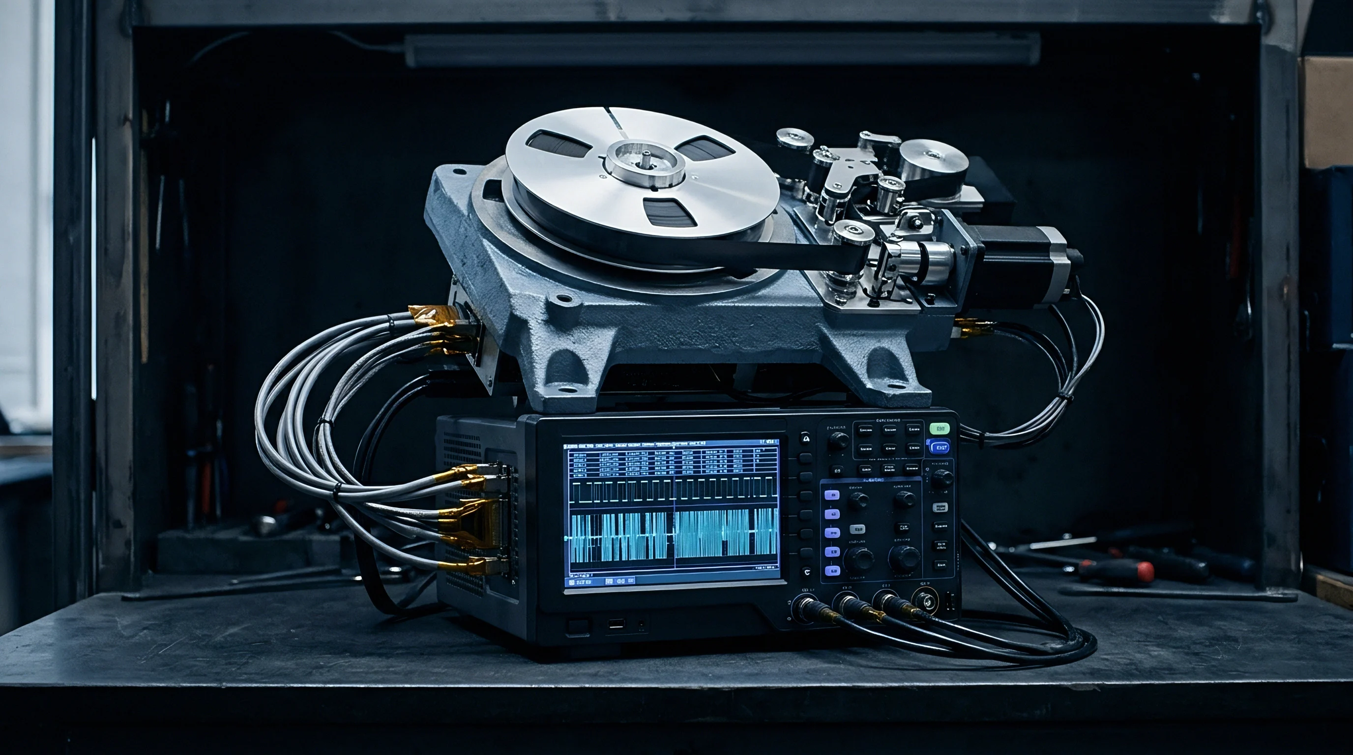
Capturing battery behavior accurately requires bench instrumentation fast enough to catch microsecond dips while holding multi-second current draws. Standard DC supplies mask passivation effects entirely because their feedback loops regulate away rail variation. Evaluating primary cells properly requires programmable electronic loads or dedicated battery emulators configured for dynamic pulsed profiles.

Bench Emulation of Multi-Second Burst Profiles
Characterization rigs rely on source measure units sampling at hundred-kilohertz rates. Cells must be conditioned at defined temperatures prior to measurement; unconditioned units pulled off room-temperature shelves yield optimistic transient curves that rarely reflect cold-weather field behavior.
Running tests at minus twenty degrees Celsius exposes actual operational margins under maximum repetition profiles, particularly since cold conditions can double cell internal resistance. Electronic loads need to emulate full LTE-M and NB-IoT transmission windows, sinking rated current for up to ten seconds while logging the transient voltage floor.

Procurement Specification Standards
Qualifying primary cells purely on nominal milliamp-hour ratings invites early field failures. Sourcing contracts need clear parameters for pulse drain capability, transient minimum voltage, maximum equivalent series resistance, and pre-deployment storage conditions. Requiring lot-specific depassivation logs or pulse test reports provides baseline quality assurance before production volumes ship.
Tight incoming inspection procedures help intercept sub-par battery lots before they reach the assembly floor. Procurement agreements ought to specify statistical lot sampling under multi-second pulse loads that mirror target cellular transmission profiles.
Writing an enforceable transient minimum voltage specification for multi-second loads directly into procurement agreements ties cell quality to vendor accountability if modules drop out prematurely.