Subterranean Radio Propagation Path Loss Basics
Subterranean radio links require sub-GHz carriers and massive fade margins to overcome decibel-per-meter soil absorption, boundary refraction, and antenna detuning.


Soil
Subterranean RF propagation breaks with free-space calculations immediately: the transmission medium is lossy, its dielectric permittivity shifts with frequency, and magnetic conductivity is rarely zero. In utility metering, pipeline monitoring, and borehole instrumentation, signal decay is clocked in decibels per meter rather than per kilometer. Bulk earth acts as an attenuator where displacement and conduction currents compete directly, driven by volumetric water content, dissolved salts, soil density, and operating wavelength.
Dry quartz sand has a relative dielectric constant near 3.0 and electrical conductivity under 0.001 Siemens per meter, so lower-frequency fields can travel tens of meters through it. Saturated clay loam with brackish pore water inverts those constants: relative permittivity climbs past 35 while bulk conductivity exceeds 0.5 Siemens per meter. As operating frequencies rise above 300 MHz, molecular relaxation of the water dipole drives dielectric losses up sharply.
Coarse dry sand allows tenfold greater penetration distance than saturated bentonite clay at identical radio frequencies.
Mineral composition sets baseline charge migration. Montmorillonite clays contain active ion-exchange sites that hold thin films of saline water tightly against silicate platelets, producing strong Maxwell-Wagner interfacial polarization at radio frequencies. Quartz gravel lacks these exchange sites entirely.
Ground propagation velocity drops with the square root of the real relative permittivity, compressing wavelengths to a small fraction of their free-space values. A 433 MHz carrier, with a 69-centimeter wavelength in air, shrinks to roughly 11 centimeters in wet ground, fundamentally altering the electrical size and input impedance of any buried antenna.

Dielectric Modeling Mechanisms
Engineers calculate underground propagation by treating soil as a lossy dielectric characterized by complex relative permittivity. Wave velocity and stored energy depend on the real component; dielectric absorption and ohmic loss fall under the imaginary term. The Peplinski semi-empirical model maps sand and clay fractions, bulk density, and volumetric water content directly into complex permittivity from 300 MHz to 1.3 GHz.
Below this band, ionic conduction dominates dissipation, and attenuation tracks bulk conductivity almost directly.
Seasonal temperature shifts alter these dynamics. Water locked into permafrost freezes dielectric relaxation in place, dropping effective relative permittivity toward 4.0 and clearing up path loss during cold months. Thaw reverses the effect.
As liquid boundary layers reform, baseline path loss across an identical run can surge 40 dB within three weeks. Transceivers calibrated during dry late-summer surveys quietly drop off gateway logs during spring thaw.
Buried sensing nodes demand link budgets engineered against the wettest projected ground conditions rather than annual averages.


Decay
Subsurface path loss separates into three terms: bulk medium absorption, spherical spreading loss scaled by the shortened underground wavelength, and boundary refraction mismatch. The attenuation constant alpha, expressed in Nepers per meter, defines the exponential dissipation of field amplitude along the propagation vector. Converting alpha to decibels per meter shows why standard industrial frequency bands carry severe range penalties underground.

Absorption versus Spreading
Ohmic conduction dominates attenuation at low frequencies, but dielectric relaxation takes over once carriers enter UHF bands. Plane wave attenuation follows the complex propagation constant derived from Maxwell equations for lossy media. Underground spreading loss accumulates at 20 decibels per decade of distance ~ algebraically identical to free space, though scaled by phase velocity inside the dielectric matrix.
Because phase velocity drops by factors between three and eight depending on moisture, near-field zones compress tight against the radiating element.
Calculating the attenuation coefficient alpha across specific ground matrices illustrates how quickly conditions alter propagation:
| Soil Type | Volumetric Moisture | Frequency | Real Permittivity | Conductivity (S/m) | Attenuation (dB/m) |
|---|---|---|---|---|---|
| Dry Sand | 2% | 169 MHz | 2.8 | 0.001 | 0.18 |
| Dry Sand | 2% | 868 MHz | 2.9 | 0.003 | 0.62 |
| Sandy Loam | 15% | 169 MHz | 9.4 | 0.025 | 4.30 |
| Sandy Loam | 15% | 868 MHz | 8.8 | 0.040 | 14.80 |
| Silty Clay | 30% | 169 MHz | 22.5 | 0.120 | 18.50 |
| Silty Clay | 30% | 433 MHz | 20.8 | 0.160 | 31.20 |
| Silty Clay | 30% | 868 MHz | 18.9 | 0.210 | 58.40 |
| Saturated Clay | 45% | 915 MHz | 34.2 | 0.480 | 108.60 |
| Saturated Clay | 45% | 2400 MHz | 31.0 | 0.950 | 242.00 |
At 2.4 GHz in saturated agricultural soil, path loss exceeds 240 decibels over just one meter of transit. Radios operating under Bluetooth or 2.4 GHz Zigbee protocols achieve zero usable underground-to-underground penetration across two meters of wet clay, regardless of receiver sensitivity. Sub-GHz spectrum represents the only viable commercial choice for deep soil deployment.
A 14-decibel path loss increase per additional meter of wet loam eliminates standard industrial link margins inside three meters of total burial depth.
Wave impedance falls as soil permittivity climbs. Air has an intrinsic impedance of 377 Ohms, whereas wet silty clay drops below 60 Ohms. This discontinuity reflects energy away whenever incident waves hit mineral boundaries or buried structural obstacles, draining power from the intended transit path.

Where Does Soil Moisture Break Transmission?
Permittivity increases sharply once water saturation crosses transition moisture thresholds, typically between 12 percent and 18 percent volumetric content. Below that point, bound water molecules adhere directly to soil particle surfaces through hydrogen bonding, held rigid with limited rotational freedom and contributing modestly to loss. Once hydration layers exceed two molecular thicknesses, unbound free water fills pore spaces.
These free molecules rotate under high-frequency alternating electric fields, driving up the dielectric loss tangent.
A transmitter buried one meter deep in sandy loam delivering plus 14 dBm into an isotropic element operates comfortably during dry spells. If irrigation raises volumetric moisture to 20 percent, total attenuation through that single meter jumps from 2.5 dB to roughly 22 dB, immediately dropping packets. System designers counter this either with substantial fade margins or by selecting lower carrier frequencies that tolerate moisture swings.
Field investigations often stall over whether seasonal dropouts stem from localized moisture pooling around the antenna housing or broader water-table shifts across the line of sight.


Interface
Buried transmitters communicate with aboveground base stations far more often than with peer subsurface radios. This underground-to-aboveground link topology (UG-to-AG) forces the wavefront across the sharp discontinuous boundary separating soil from free air. The transition imposes Snell refraction, Fresnel transmission loss, and internal reflection constraints that govern link feasibility.
Refraction compresses subterranean rays toward the surface normal. Because soil has a much higher refractive index than air, waves traveling upward bend sharply outward upon emergence. Snell’s law dictates that only waves striking the interface within a narrow critical angle escape into the atmosphere; in moist terrain, this critical angle theta is often narrower than 15 degrees.
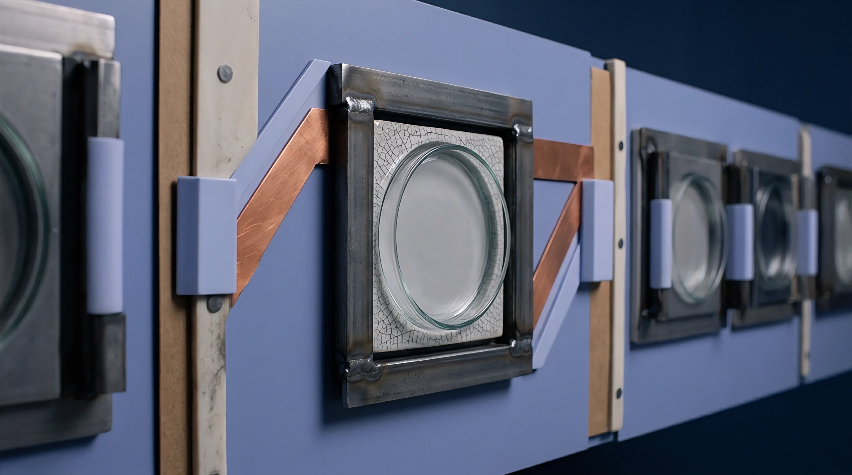
Critical Angle Dynamics
Radiation striking outside the critical cone undergoes total internal reflection, turning back into the ground matrix. The soil-air boundary behaves like a spatial aperture, restricting usable signal projection to a narrow vertical cone centered directly above the buried node. Aboveground gateways mounted at distant horizontal offsets receive negligible direct refracted energy from a deeply buried node.
Fresnel transmission coefficients determine how much power actually breaches this exit cone. Polarization shifts the outcome: parallel polarized waves (transverse magnetic) pass through the boundary with lower reflection losses near Brewster’s angle, while perpendicular polarized waves (transverse electric) suffer persistent reflection across all incident trajectories. Horizontally buried antennas generate predominantly transverse electric fields at the ground surface, introducing up to 18 dB of additional interface reflection loss into the link budget.
The boundary mechanism resolves field links into three distinct propagation modes:
- Direct Refracted Waves penetrate through the interface within the critical cone and propagate straight to receiving gateway antennas within visual clearance.
- Lateral Surface Waves travel upward from the buried source to the boundary, refract along the interface line on the air side at the speed of light, and shed energy back downward into the earth while radiating outward across the surface terrain.
- Reflected Ground Waves bounce downward off the surface interface, scattering into deep strata layers until mineral absorption extinguishes field intensity completely.

Why Do Lateral Waves Dominate Surface Reception?
Gateway equipment positioned hundreds of meters away from a buried sensor relies almost exclusively on lateral waves rather than direct subterranean rays. A direct path through soil would have to cross dozens of meters of lossy earth, accumulating hundreds of decibels of medium absorption. The lateral wave takes the shortest vertical path to the surface, breaches the soil crust within the critical boundary window, and skims horizontally across the air layer where attenuation follows the low free-space exponent.
Lateral waves survive across extended horizontal distances because energy transits the low-loss air layer rather than dense subterranean strata.
Path loss for this lateral path is calculated using a three-segment model. Segment one covers vertical attenuation through depth d at the soil alpha rate. Segment two covers boundary transmission loss across the air-soil transition zone.
Segment three covers free-space spreading over horizontal distance r, modified by ground-proximity terrain clutter. Placing the transmitter shallowly beneath the surface reduces segment-one absorption, allowing lateral waves to form with minimal initial loss.
Installing underground sensors at excessive depths to avoid frost lines often drops the transmitter below the lateral wave launch threshold, causing remote gateways to lose packet reception across all operational channels.

Topology
Hardware selection governs underground link survival. Buried antennas encounter heavy dielectric loading from surrounding earth, which detunes resonance downward and drops radiation efficiency into single-digit percentages. A standard quarter-wave monopole tuned for 868 MHz in air drops its natural resonance below 300 MHz when encapsulated in moist soil without a dedicated dielectric buffer casing, reflecting most power back into the transceiver power amplifier.

Antenna Encapsulation Design
Dielectric enclosures isolate radiating metal traces from direct soil contact. High-density polyethylene or polyoxymethylene housings with wall thicknesses of 10 to 25 millimeters push the lossy soil boundary outward from the antenna near-field zone. This physical displacement preserves antenna radiation resistance and limits reactive dissipation into damp earth.
Bare antennas placed directly into mud suffer efficiency penalties surpassing 25 dB relative to identical elements inside air cavities.
Magnetic dipole antennas, specifically insulated loop structures, demonstrate marked resilience in conductive subterranean environments. Electric dipoles couple capacitively to soil conduction paths, causing rapid near-field detuning and ohmic dissipation. Magnetic loops couple inductively, maintaining impedance stability and radiating efficiently through conductive groundwater films where electric dipoles experience complete near-field shorting.

Protocol Budget Arithmetic
Evaluating commercial transceivers demands reconciling transmit power, receiver sensitivity, receiver bandwidth, and packet airtime against battery reserves. The maximum permitted transmit power in European 868 MHz bands sits at plus 14 dBm (25 mW), while North American 915 MHz allocations permit up to plus 30 dBm under frequency-hopping spread-spectrum rules. Lower bandwidth modulations elevate receiver sensitivity, creating the link margin required to survive soil absorption.
A worked link budget demonstrates transceiver capabilities across a two-meter subterranean-to-surface baseline through moist loam soil, assuming an 868 MHz carrier, volumetric water content of 15 percent, and a horizontal gateway distance of 150 meters:
- Transmit Output Power delivers plus 14 dBm from the transceiver output pin into the matched matching stage.
- Subterranean Antenna Gain yields minus 12 dBi after accounting for dielectric casing mismatch and surrounding ground absorption.
- Vertical Soil Absorption extracts 29.6 dB over two meters of depth based on a 14.8 dB per meter attenuation constant.
- Soil Surface Interface Loss subtracts 11.4 dB in Fresnel transmission attenuation and polarization mismatch.
- Surface Air Spreading Loss consumes 74.8 dB across the 150-meter air path to the receiver mast.
- Gateway Antenna Gain adds plus 5 dBi from an elevated mast-mounted collinear array.
- Net Received Signal Power settles at minus 108.8 dBm at the receiver radio input port.
Standard 250 kbps FSK radios exhibit sensitivity floors around minus 102 dBm, failing to decode this signal. A LoRa transceiver operating at spreading factor 10 with a 125 kHz bandwidth holds sensitivity down to minus 132 dBm, leaving an operating margin of 23.2 dB to absorb seasonal moisture swings. Ultra-narrowband modulations like 100 bps UNB or NB-IoT carrier allocations push sensitivity floors lower, yet require extended transmission intervals that strain cell batteries.
| Protocol Tier | Nominal Band | Transmit Power | Air Sensitivity | Current Draw | Soil Range (Moist) |
|---|---|---|---|---|---|
| Proprietary FSK | 433 MHz | +10 dBm | -105 dBm | 22 mA TX | 1.5 to 3.0 m |
| LoRaWAN (SF12) | 433 MHz | +14 dBm | -136 dBm | 35 mA TX | 4.0 to 9.0 m |
| LoRaWAN (SF10) | 868 MHz | +14 dBm | -132 dBm | 30 mA TX | 2.0 to 5.0 m |
| LoRaWAN (SF10) | 915 MHz | +22 dBm | -132 dBm | 110 mA TX | 3.5 to 7.0 m |
| Cellular NB-IoT | Band 20 (800) | +23 dBm | -135 dBm | 220 mA TX | 3.0 to 6.5 m |
| BLE 5.0 (Coded PHY) | 2400 MHz | +8 dBm | -103 dBm | 12 mA TX | 0.2 to 0.6 m |
High packet airtimes drain primary batteries rapidly. A LoRa packet transmitted at spreading factor 12 occupies over one second of continuous radio frequency emission. Subsurface utility meters relying on lithium thionyl chloride cells face sharp voltage drops when pulsed with high peak currents at low ground temperatures.
Engineers frequently throttle transmission schedules to a single daily transmission to ensure a ten-year cell longevity profile.
Enclosure vapor ingress is often blamed for link dropouts where the true loss is the 20-decibel absorption surge caused by compacted trench backfill.


Appraisal
Specifying modules for subsurface deployment requires rigorous procurement audits covering silicon performance, regulatory conformity, and assembly tolerances. Radios operating underground cannot be serviced without excavating earth, turning field maintenance into an expensive civil engineering task. Sourcing teams prioritize transceiver phase noise, frequency stability across thermal swings, and guaranteed transceiver input impedance under variable ground planes over raw catalog unit pricing.
Thermal and Packaging Stability
Burying hardware protects electronics from severe aerial temperature swings yet exposes cases to sustained moisture vapor pressure. Water vapor migrates through standard potting compounds over multi-year periods, causing micro-condensation on radio frequency traces. Silica-filled polyurethane or low-permeability epoxy resins isolate radio boards from vapor infiltration, preventing shifts in board dielectric properties.
Silicon vendors must supply industrial-grade chips rated from minus 40 to plus 85 degrees Celsius, outfitted with temperature-compensated crystal oscillators to counter drift.
Frequency drift destroys narrowband links. An ultra-narrowband transmitter operating with a 1 kHz receiver channel bandwidth drops completely out of detection windows if the reference crystal drifts by 5 parts per million over seasonal thermal gradients. Temperature-compensated crystals add roughly 0.45 dollars to bill-of-materials costs yet eliminate missed packet events.
Sourcing agreements must explicitly state crystal stability bounds across the full operating range.

Regional Compliance Constraints
Radio spectrum rules limit transmission power and duty cycles based on jurisdiction. European deployments governed by ETSI EN 300 220-2 restrict 868 MHz devices to a 1 percent duty cycle ceiling across standard sub-bands, limiting maximum hourly transmissions. The 169 MHz VHF band, reserved under European rules for remote utility metering, allows up to 500 mW (+27 dBm) transmit power under specific channel arrangements, offering superior soil penetration due to minimal medium attenuation.
North American installations under FCC Part 15.247 permit frequency-hopping transmitters to broadcast up to plus 30 dBm across 902 to 928 MHz, yielding an eight-decibel link margin advantage over European equivalents. This regulatory power margin compensates directly for the elevated attenuation constant observed in moist North American clay soils.
Procurement teams protect field margins by inserting specific qualification thresholds into module supply contracts:
- Confirm receiver sensitivity testing conducted inside real dielectric dummy loads mimicking saturated sand and clay mixtures rather than 50-Ohm bench instruments.
- Enforce crystal tolerance limits below 1.5 parts per million across the thermal excursion profile from minus 20 to plus 60 degrees Celsius.
- Verify housing potting compound ingress ratings under IP68 test conditions at continuous three-meter immersion depth for 1,000 continuous hours.
- Mandate trace impedance certification on radio frequency output pins after conformal encapsulation to prevent board-level reflections.
Sourcing agreements that bind suppliers to standard open-air production acceptance tests forfeit warranty claims when modules fail to maintain connection links beneath six inches of wet agricultural topsoil.