Regulatory Risk Assessment of Enclosure Retesting Fees in Global Certification Launches
Modifying enclosure materials or geometry shifts near-field coupling and radiated emissions, triggering mandatory global re-testing and permissive change refilings.

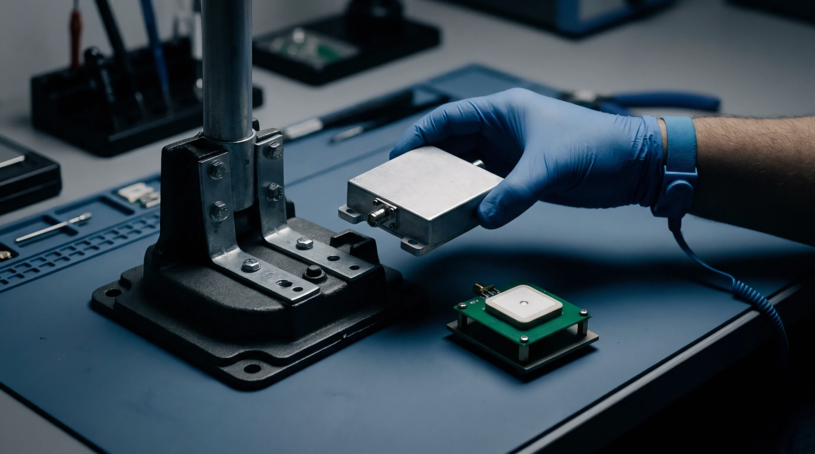
Shell
Late mechanical alterations change a wireless device’s internal electromagnetic environment. Modular transmitter approvals rely on boundary conditions established during reference testing. Switching an enclosure from unfilled polycarbonate to a mineral-filled resin or die-cast aluminum alters near-field impedance around the antenna.
Shifts in the dielectric constant move the resonant frequency of internal trace antennas, while conductive surfaces change radiation patterns and input impedance. This turns an approved sub-assembly into a modified system that no longer matches its baseline filing.
Thinner housing walls narrow the gap between internal circuit boards and the outer enclosure boundary. Shifting a metallic shield or ground plane 1.5 millimeters closer to a microstrip line alters parasitic capacitance, detuning matching networks, shifting power amplifier loading, and generating unexpected harmonics. In semi-anechoic chambers, even non-conductive enclosures interact with RF energy; polymer loss tangents absorb or reflect energy based on resin chemistry, filler ratios, and moisture levels.

Dielectric Shifts in Polymeric Materials
Engineering thermoplastics carry distinct dielectric profiles. Unfilled polycarbonate maintains a relative permittivity near 3.0 with a loss tangent of 0.001 at 2.4 GHz. Switching to a glass-filled variant for extra rigidity pushes permittivity to 3.5 and loss tangent to 0.004, altering the phase velocity of waves passing through the enclosure wall.
Radiating elements within one quarter-wavelength of that inner wall detune, shifting antenna center frequency and degrading return loss.
| Polymer Resin Grade | Filler Percentage | Dielectric Constant at 2.4 GHz | Loss Tangent at 2.4 GHz | Observed Antenna Frequency Shift |
|---|---|---|---|---|
| Unfilled Polycarbonate | 0% | 3.02 | 0.0012 | Baseline reference |
| Glass-Filled PC/ABS | 20% Glass Fiber | 3.48 | 0.0045 | Down shift by 42 MHz |
| Mineral-Filled Polypropylene | 30% Talc | 2.85 | 0.0021 | Up shift by 18 MHz |
| Flame-Retardant PBT | 15% Halogen-Free | 3.31 | 0.0078 | Down shift by 31 MHz |
Flame-retardant additives introduce localized dielectric variations across molded parts. Brominated compounds and aluminum trihydrate fillers settle unevenly in high-cavity injection molds. Weld lines formed near tooling gates reduce local resin density, creating anisotropic dielectric zones directly above integrated antennas.
In chamber scans, these weld lines distort beam symmetry and cross-polarization rejection, showing up as drops or shifts in total radiated power and isotropic sensitivity.
Hydrophilic polymers like polyamide absorb moisture, destabilizing RF performance over time. Polyamide 6,6 absorbs up to 8 percent water by weight under high humidity. With water’s relative permittivity near 80 at 2.4 GHz, a saturated wall sharply increases the effective dielectric constant, pulling antenna resonance down and adding 3 dB to 6 dB of insertion loss across the band.
Dry, freshly molded prototypes tested during pre-compliance miss this shift entirely, leaving projects vulnerable during final accredited certification.
Radiated spurious emissions increase by 4.2 dB at the third harmonic when replacing PC-ABS with conductive polyolefin without recalculating ground plane stitch spacing.

Slot Resonances across Structural Apertures
Housing seams, display openings, and vent arrays turn into accidental slot antennas when excited by high-frequency internal currents. A conductively painted plastic seam forms a resonant slot if contact breaks between mating faces. When gap length reaches half the guided wavelength of an internal harmonic, it radiates efficiently.
At 5.8 GHz, a 25.8-millimeter seam gap creates a half-wave slot antenna that dumps board noise straight into space as radiated emissions.
Perimeter screw spacing determines seam impedance at RF. Placing screws 50 millimeters apart leaves gaps that flex under thermal expansion or drop impacts. If conductive gaskets lose continuous contact, high-power transmitters nearby drive non-linear intermodulation.
Shielding calculations must account for slot geometry alongside material attenuation; digital traces running parallel to housing seams induce surface currents that leak through gaps and push emissions past EMC limits.
Display cutouts and optical windows open gaps in shielding. Indium tin oxide on glass provides transparency with surface conductivity, but thinning the layer for better light transmission increases sheet resistance from 10 ohms per square to 100 ohms per square. That tenfold jump drops shielding effectiveness by about 20 dB, letting display driver clocks radiate through the front panel.

Potting Compounds and Antenna Detuning
Potting internal electronics for ingress protection alters the RF environment completely. Silicone, epoxy, and polyurethane displace air around microstrips and chip antennas. Epoxy resins carry dielectric constants between 3.5 and 4.5; coating an antenna tuned for air drops its resonant frequency over 15 percent, knocking the radio out of its assigned band.
Thermally conductive encapsulants with ceramic fillers boost heat transfer but shift permittivity. Fillers like aluminum oxide or boron nitride raise dielectric constants above 5.0. Filling cavity space with these resins alters transmission line impedance ~ a 50-ohm microstrip drops to 38 ohms under ceramic potting, creating impedance mismatches, high standing wave ratios, and extra heat in the power amplifier stage.
Liquid potting expands and shrinks while curing, forming voids along PCB surfaces near RF lines. These air pockets cause batch-to-batch variations in dielectric constant. A unit cured warm responds differently than one cured at room temperature, and test labs catch those discrepancies during certification ~ triggering redesigns and repeat chamber runs.
Cosmetic resin changes frequently alter electrical performance: color masterbatches with carbon black or metallic flakes turn non-conductive plastics into lossy RF attenuators.
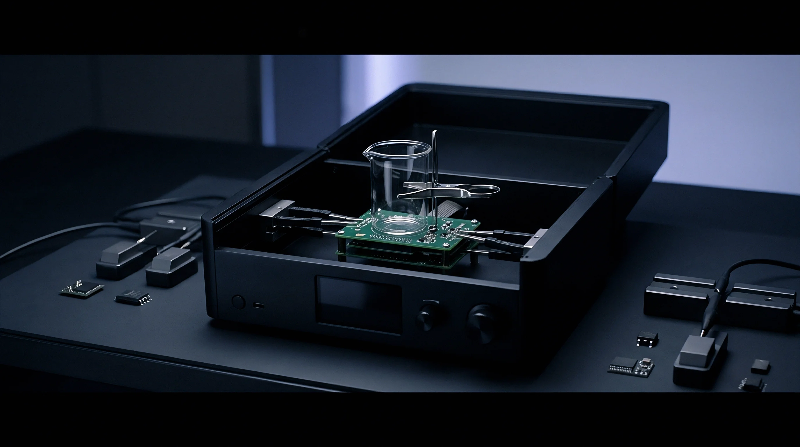

Harmonics
Spurious emissions are the single most common failure during enclosure retesting. Unwanted radiation from digital switching, power converters, and transmitter harmonics leaks through mechanical gaps in modified housings. Standards strictly cap out-of-band emissions to protect adjacent spectrum.
When housing geometry changes, internal coupling shifts with it, putting existing compliance reports at risk.
Emissions testing covers broad frequency ranges, sweeping from 30 MHz up to the tenth harmonic of the highest fundamental. On a 5.8 GHz Wi-Fi 6E product, sweeps reach 40 GHz. Enclosure tweaks that look harmless at 2.4 GHz can open up strong radiation paths at 12 GHz or 24 GHz, where shorter wavelengths match small cavity dimensions and minor apertures.

Turntable Azimuth Scans and Peak Spurious Traces
Accredited emissions testing uses semi-anechoic chambers fitted with automated turntables and antenna masts. Samples rest on non-conductive mounts 0.8 meters above the ground plane below 1 GHz and 1.5 meters above it for higher frequencies. The turntable spins 360 degrees while the antenna scans vertically from 1 to 4 meters, mapping peak radiation vectors from every angle.
Changing housing geometry shifts the shape and direction of spurious radiation lobes. Adding internal ribs to a metal chassis alters internal reflection patterns, sending emissions toward elevation angles that were quiet during original testing. If baseline peaks appeared horizontally at 15 degrees, the modified case might reflect energy vertically at 45 degrees, hitting the antenna with levels above statutory limits.
Chamber sweeps use peak, quasi-peak, and average detectors. Quasi-peak detectors weight signals by repetition rate to spot periodic digital bus noise, while average detectors measure continuous harmonic energy from transmitters. Shielding changes that let raw memory clock noise interact with housing resonances can turn broadband noise into sharp spikes exceeding both peak and quasi-peak limits.

Restricted Band Emissions under ETSI and FCC
Restricted bands carry strict absolute emission limits to protect essential services. Under FCC Part 15.205 and 15.209, field strength above 960 MHz cannot exceed 500 microvolts per meter at 3 meters, which equals -41.3 dBm EIRP. In Europe, ETSI EN 300 328 Clause 4.3.2.9 caps transmitter spurious emissions at -30 dBm and standby emissions at -47 dBm.
| Regulatory Standard | Frequency Range | Detector Type | Field Strength / Power Limit | Measurement Distance |
|---|---|---|---|---|
| FCC Part 15.209 | 30 MHz – 88 MHz | Quasi-Peak | 100 uV/m (40.0 dBuV/m) | 3 meters |
| FCC Part 15.209 | 216 MHz – 960 MHz | Quasi-Peak | 200 uV/m (46.0 dBuV/m) | 3 meters |
| FCC Part 15.205 / 15.209 | Above 960 MHz (Restricted) | Average | 500 uV/m (54.0 dBuV/m) | 3 meters |
| ETSI EN 300 328 Clause 4.3.2.9 | 1 GHz – 12.75 GHz (Tx Mode) | Peak / Average | -30 dBm EIRP | 3 meters |
| ETSI EN 300 328 Clause 4.3.2.10 | 47 MHz – 74 MHz (Standby) | Quasi-Peak | -54 dBm EIRP | 3 meters |
Restricted band rules leave little headroom. A design that passed original testing with a 2 dB margin will fail if housing alterations add 2.5 dB of emission. Dropping carbon shielding additives from a plastic resin lets power converter harmonics bleed directly into aeronautical or navigation bands.
When test labs hit these failures, testing stops until engineering issues fix orders and re-books chamber time.
Accurate field strength figures depend on antenna factors and cable loss data. Spectrum analyzers convert raw voltage into field strength using factors specific to each horn antenna. At high frequencies, cable loss mounts fast ~ a 10-meter coax run at 18 GHz can drop signal level by 8 dB.
If a lab forgets to update cable loss tables during testing, reported margins are wrong, creating false passes that audit reviews inevitably reject.

Cavity Resonance Shifts in Metallic Housings
Metallic or metallized enclosures act as cavity resonators. The physical dimensions inside the chassis define resonant frequencies where fields form standing waves. For a rectangular cavity, that fundamental frequency depends on internal length, width, and height.
Trimming cavity height by just 2 millimeters during a redesign shifts that resonance higher.
If cavity resonance shifts into alignment with a clock or radio harmonic, the housing amplifies emissions instead of blocking them. Internal fields build up, driving high surface currents along conductive walls that leak out through seams, cable ports, and screw holes. For instance, a 1.2 mm clearance reduction causes the fifth harmonic of a 2.4 GHz transmitter to lock onto the cavity’s TE101 mode, spiking radiated emissions by 18 dB.
Fixing cavity resonance takes field damping or physical geometry changes. Internal microwave absorbers soak up RF energy and turn standing waves into heat, though they add unit cost and assembly steps. Alternatively, adding grounding posts or spring fingers between the metal walls and circuit board ground shifts boundary conditions, moving cavity resonance away from sensitive harmonics.
How far can an engineering team move an internal metal partition before cavity resonance hits the second harmonic of an integrated radio module?


Amendment
Regulatory agencies enforce clear rules for post-certification product changes. Modifying an enclosure triggers obligations to report, re-test, or re-certify depending on the scale of the change. Authorities group structural edits into permissive change tiers or demand a full new application.
Knowing these boundaries determines whether a modified product can stay on an existing grant or needs a new ID.
Empirical test data separates minor administrative updates from major technical refilings. Host manufacturers must prove enclosure modifications preserve EMC and RF safety compliance. Trying to slip changes through under the wrong classification risks sales halts, customs holds, and heavy fines from market surveillance authorities.

Permissive Change Thresholds in FCC and ISED Filings
The FCC and ISED handle post-grant alterations through Permissive Change tiers. Guidance in FCC KDB 996369 D02 and D04 requires host products using modular transmitters to follow original grant conditions strictly. If an enclosure change alters the space around a module or shifts antenna separation distances, filing status must be re-evaluated.
- Class I Permissive Change applies when enclosure changes show no degraded RF characteristics, keeping power, harmonics, and exposure profiles identical to baseline data.
- Class II Permissive Change requires filing accredited test data with a TCB when changes degrade radiated emissions or alter antenna patterns while staying within statutory limits.
- Class 4 Permissive Change under ISED RSS-Gen covers modular alterations where host enclosure changes affect compliance, requiring documentation updates on the Radio Equipment List.
- New FCC ID Application is required if enclosure modifications force changes to PCB layout, antenna geometry, or power levels past certified limits.
Filing a Class II Permissive Change (C2PC) means submitting updated spurious emissions data, SAR reports, and operational descriptions to the TCB. The TCB checks the technical file to verify that new enclosure boundaries satisfy authorization rules. Products cannot ship in the updated housing until the TCB issues the updated grant.

Does Plastic Material Substitution Trigger Complete Radiated Spurious Retesting?
Sourcing teams aiming to cut resin costs often treat plastic swaps as trivial. But changing resins alters shielding, internal near-field coupling, and dielectric constants. Regulators view material changes as potential compliance risks.
If an original filing relied on conductive resin or metallic coating to pass emissions, moving to un-metallized plastic invalidates that compliance report.
Establishing retest scope starts with spot-check radiated scans in an accredited chamber across worst-case operating modes from the baseline report. If spot checks show spurious emissions rising more than 3 dB above original figures, the lab expands testing to cover full radiated spurious across all operating bands. That resulting report forms the basis of the Permissive Change submission.
Resin formula changes made without owner notification create serious legal exposure. Certification grants belong to the grantee of record, who remains legally accountable for field compliance. Surveillance programs regularly buy retail units, strip the housings, and check material composition with X-ray fluorescence.
Unapproved deviations trigger formal violation notices and mandatory recalls.
Regional Filing Rules across Asian Regulatory Authorities
Asian regulatory regimes enforce strict procedures for housing modifications. Unlike European self-declaration paths, regulators in China, Japan, and South Korea require explicit agency notification and formal file amendments before modified hardware can be sold.
| Target Region | Regulatory Body | Filing Classification | Local Testing Mandatory? | Typical Filing Approval Lead-Time |
|---|---|---|---|---|
| United States | FCC / TCB | Class II Permissive Change | No (Any ISO 17025 Lab) | 1 to 2 Weeks |
| European Union | Notified Body / RED | TCF Update & Risk Assessment | No (Self-Declaration / CE) | Immediate to 1 Week |
| China | SRRC | Certificate Modification | Yes (In-Country Accredited Lab) | 4 to 6 Weeks |
| Japan | MIC / CAB (Giteki) | Construction Type Amendment | Conditional on RF Impact | 2 to 3 Weeks |
| South Korea | MSIT / RRA (KC) | Conformity Registration Revision | Yes (In-Country Testing) | 3 to 5 Weeks |
China’s SRRC enforces strict modification rules. Any structural change affecting housing shielding, antenna positioning, or internal volume requires retesting inside an accredited Chinese lab. SRRC rejects test reports generated outside China, forcing manufacturers to ship physical units directly to facilities in Beijing or Shenzhen, with fees assessed per modified variant.
Japan’s MIC handles Giteki certification through Registered Certification Bodies (CABs). When housing changes alter physical construction, the grantee files an Application for Amendment of Construction Type Certification. If the CAB finds antenna placement shifted relative to outer walls, they will demand spot-check retesting of EIRP and spurious emissions before issuing the amendment.
South Korea’s RRA mandates KC registration revisions for enclosure changes under the Radio Waves Act. Manufacturers submit technical descriptions of the modifications along with EMC reports from designated Korean labs. Distributing modified units without an updated KC registration risks fines up to 10 million KRW and inventory seizure at customs.
Under Clause 4.1.2 of the master supply agreement, unapproved changes to resin formulations, metallic coatings, or wall dimensions void supplier indemnification against regulatory non-compliance liabilities.


Exposure
Enclosure dimensions directly affect human exposure profiles. Devices operating within 20 centimeters of the body undergo Specific Absorption Rate (SAR) testing to measure RF absorption in biological tissue. Thinner enclosure walls move radiating elements closer to skin, driving localized SAR up sharply under near-field exposure mechanics.
Near-field RF energy attenuates rapidly with distance ~ localized E-field strength scales inversely with the square or cube of separation distance, depending on antenna geometry. Trimming plastic wall thickness from 3.0 millimeters to 1.5 millimeters cuts antenna-to-skin distance in half. That physical change can push peak 1-gram SAR past regulatory limits, turning a compliant product into an unauthorized transmitter.

Separation Distances and Localized SAR Hotspots
SAR compliance targets peak spatial-average absorption in watts per kilogram (W/kg). Limits sit at 1.6 W/kg over 1 gram of tissue in North America under FCC KDB 447498 D01, and 2.0 W/kg over 10 grams in the EU under EN 50566. Small housing changes shift internal field patterns, concentrating energy into localized hotspots near antenna feeds.
- Spatial Geometry Assessment measures antenna clearance to housing walls using 3D CAD modeling.
- Dielectric Coupling Analysis models how resin permittivity shifts alter RF field propagation into tissue phantoms.
- Vector Probe Pre-Scanning locates peak field intensity across the outer housing surface.
- Full DASY Phantom Testing measures 1-gram and 10-gram localized SAR inside tissue-simulating liquid at maximum power.
- Power Back-off Implementation updates firmware power tables if housing changes push SAR past statutory limits.
Enclosure-induced antenna detuning shifts impedance matching, driving up transmitter current draw or altering power distribution. If dynamic power control is active, impedance mismatches can lock the transmitter at maximum output continuously. That drains batteries faster while generating extra localized heat, complicating thermal design and SAR compliance at the same time.
Non-conductive plastics can act as dielectric lenses, focusing electric field lines through thin wall sections. Labs frequently find localized SAR spikes right under plastic ribbing or snap features. Resolving these hotspots means adding shims, applying copper tape shielding, or altering tooling ~ all of which increase unit cost and assembly steps.
Subpart C compliance under FCC Part 15.247 lapses immediately if enclosure wall thickness reductions move internal trace separation below 2.5 millimeters.

Phantom Measurements and Vector Probe Scans
Accredited SAR testing uses robotic systems operating over liquid-filled phantoms. Devices mount against flat phantoms for body-worn setups or SAM mannequins for head testing. A robot sweeps an isotropic E-field probe through a 3D grid inside the liquid, logging field strength to map localized absorption contours.
| Regulatory Body | Exposure Classification | Averaging Mass / Limit | Separation Distance Threshold | Enclosure Retest Trigger Condition |
|---|---|---|---|---|
| FCC (USA) | General Population / Uncontrolled | 1.6 W/kg (1g Tissue) | Less than 20 cm | Wall thickness reduction over 0.5 mm |
| ISED (Canada) | General Population / Uncontrolled | 1.6 W/kg (1g Tissue) | Less than 20 cm | Antenna-to-housing distance change |
| CE / RED (EU) | General Population / Body | 2.0 W/kg (10g Tissue) | Less than 5 mm | Enclosure material permittivity shift |
| MIC (Japan) | General Population / Head & Body | 2.0 W/kg (10g Tissue) | Less than 20 cm | Structural housing clearance drop |
Vector probe systems use planar arrays to map field distributions in seconds. Where traditional robotic scans take up to 30 minutes per channel, vector arrays offer quick pre-screening during design tweaks. Engineering teams use them to evaluate prototype housings before cutting production steel, catching SAR issues early when tooling changes are cheap.
Tissue-simulating liquids require property verification before every test run. Labs check permittivity and conductivity with coaxial probe kits, tuning fluid recipes to match IEC/IEEE 62209-1528 targets. If lab temperatures drift during a long run, fluid properties shift and invalidate scan data, which is why compliance engineers inspect fluid logs alongside raw data files.

Multi-Transmitter Exposure Mechanics in Refined Housings
Modern devices pack multiple simultaneous transmitters into tight housings ~ a handheld might run Wi-Fi 6E, Bluetooth, and 5G NR modems within millimeters of one another. Reducing housing volume pushes antenna elements closer, increasing mutual coupling and cross-talk.
Multi-transmitter designs must meet Peak Spatial-Average SAR Summation rules, where individual SAR-to-limit ratios are summed. Exceeding a total ratio of 1.0 triggers formal Simultaneous Transmission Analysis or spatial overlap evaluations. Moving antennas closer together increases field overlap, driving the summation ratio past 1.0 and forcing software power reductions that degrade range and throughput.
Software power back-offs alter overall product performance. A 2 dB power cut to pass simultaneous exposure limits reduces effective coverage by up to 36 percent. Product teams have to weigh that drop in range against the cost and schedule hit of redesigning the housing.
A 1.0 mm wall thin-down forced dynamic power back-offs across four cellular bands, resulting in a $34,000 redesign penalty.

Tariff
Housing modifications impact launch budgets through lab testing fees, agency tariffs, and market delay costs. Certification planning has to account for chamber daily rates, local agent retainers, and regulatory filing fees. Overlooking these cost drivers leads to budget overruns and delayed revenue across key markets.
Lab pricing reflects facility investment and technical expertise. Accredited 10-meter semi-anechoic chambers carry multi-million-dollar infrastructure costs, which drive hourly and daily rates. Controlling expenses requires clear visibility into test fee structures, sample preparation, and filing tariffs across every target market.

Accredited Chamber Pricing and Laboratory Retest Tariffs
Labs quote work based on chamber time, engineering support, and reporting requirements. Pre-compliance screening costs far less than accredited testing runs, so teams use pre-compliance scans to find failures early before spending budget on official chamber runs.
- Pre-Compliance Chamber Rate ranges from $250 to $450 per hour for uncalibrated analyzer scans and real-time engineering feedback without formal reporting.
- Accredited Radiated Chamber Rate runs $3,000 to $5,000 per 8-hour shift using calibrated 3-meter or 10-meter facilities and certified test staff.
- SAR Measurement Suite Tariff costs $2,500 to $4,200 per day, covering tissue liquid calibration, robotic setup, and multi-band probe scanning.
- Technical Report Generation Fee adds $1,200 to $2,800 per standard, covering data processing, uncertainty calculations, and formal deliverables.
Retesting campaigns require carefully prepared samples. Labs need multiple host units configured for continuous transmission across all channels, modulations, and power levels. That means loading test firmware, bringing out antenna cables for conducted verification, and supplying dedicated power inputs.
Sample failures burn chamber time fast while technicians wait for engineering to debug non-responsive units.

Government and Agency Refiling Fee Schedules
Regulatory bodies and certification agencies charge administrative fees to process authorization amendments. Costs vary widely by country, filing type, and local representation rules. Budgeting for updates means combining direct agency fees with local representative retainers across all target regions.
| Target Jurisdiction | Regulatory Filing Type | Accredited Lab Retest Fee Range | Agency / TCB Refiling Tariff | In-Country Agent Administrative Fee |
|---|---|---|---|---|
| United States (FCC) | Class II Permissive Change | $3,500 – $7,500 | $1,500 – $2,800 | Not Required |
| European Union (CE) | TCF Update & Risk File | $2,500 – $5,500 | $2,000 – $4,000 (Notified Body) | $1,000 – $2,500 (EU Rep) |
| China (SRRC) | Certificate Modification | $8,000 – $14,000 | $1,200 – $2,500 | $2,500 – $4,500 |
| Japan (MIC / Giteki) | Type Amendment | $4,000 – $8,500 | $2,500 – $4,500 | $1,500 – $3,000 |
| South Korea (KC) | Conformity Revision | $5,000 – $11,000 | $1,800 – $3,200 | $2,000 – $4,000 |
In-country representation adds recurring cost to maintaining international approvals. Regulators in South Korea, China, and Brazil require local legal entities to hold certification registrations. Foreign manufacturers without local offices hire agencies to act as certificate holders, paying admin fees to sign, submit, and archive amended technical files with regional authorities.
Certifying bodies in Asian markets refuse documentation updates without fresh local laboratory test reports.

Financial Sensitivity Model for Multi-Market Launch Delays
The cost of a retesting campaign goes well beyond lab and agency fees. Delayed launches trigger heavy financial hits from unfulfilled orders, stranded channel inventory, and missed sales windows. Evaluating retesting risks requires modeling direct technical costs against schedule impacts.
Consider a consumer device launching simultaneously across the US, EU, China, Japan, and South Korea. Projected sales sit at 20,000 units per month at a $45 net margin per unit ~ $900,000 in monthly margin. Late in tooling validation, an unapproved resin swap causes a 5 dB spike in radiated emissions at 4.8 GHz, invalidating baseline reports everywhere.
Fixing it requires modifying production tooling, molding sample parts, booking lab time, and submitting Class II Permissive Changes along with international amendments. Chamber retesting and shipping take 3 weeks. SRRC lab testing in China and KC filings in South Korea add 5 more weeks due to lab queues and administrative reviews.
Asian launches slip by 8 weeks, while US and European launches delay by 4.
Financial losses pile up fast. Missed US and EU margin over 4 weeks totals $450,000. Missed Asian margin over 8 weeks reaches $360,000.
Lab retesting, TCB charges, and SRRC/KC tariffs add $48,500. Air freight to expedite delivery after certification costs $22,000, and rush mold modifications cost $15,000. Total impact: $895,500 ~ dwarfing the $12,000 resin savings that prompted the change.
Budgeting for pre-compliance screening during initial tooling trials prevents downstream delays by catching structural failures before committing to production tooling.


Staging
Managing regulatory risk across global launches calls for a structured rollout. Staging balances market sequence against regional filing lead-times. Establishing engineering freezes, running pre-compliance screening, and putting firm compliance terms into supplier contracts keeps launch schedules from getting derailed by unexpected retesting fees.
Regulatory compliance sits directly on the critical path of hardware development schedules. Engineering teams must treat physical housings as integrated RF components under strict change control. Proactive verification ensures mechanical tweaks happen without putting international approvals at risk.

Pre-Compliance Screening Protocols Prior to Tooling Freeze
Managing retesting risk starts long before cutting production steel. Teams build soft tooling or SLA prototypes to evaluate RF behavior early on. Coating prototype cases with nickel-acrylic conductive paint lets engineers measure shielding effectiveness and spot seam resonances before investing in multi-cavity tooling.
Pre-compliance testing focuses on high-risk parameters: total radiated power, antenna return loss, and spurious emissions at max power. Finding antenna detuning or seam leakage on a soft prototype lets engineers adjust ribbing, wall thickness, or fastener placement for a fraction of what hard tooling changes cost.
Material verification validates resin dielectric properties before production molding. Sourcing teams collect material test sheets from compounders to check permittivity and loss tangent against simulation models. Spot-checking raw resin pellets via coaxial cavity perturbation keeps batch variations within tolerance before loading tools.

Sequential Access Rollout and Lead-Time Buffer Management
Simultaneous global launches carry high schedule risk if compliance issues pop up late. Staged rollouts sequence filings by lead-time, report reusability, and market priority. Securing early approvals in regions that accept self-declarations or fast-track TCB reviews generates revenue while longer international filings move through the pipeline.
- Primary Baseline Approval Tier obtains the FCC Grant and EU CE Declaration of Conformity from baseline laboratory test files.
- Secondary Leverage Tier uses ISO 17025 accredited baseline reports to apply for Canada (ISED), Taiwan (NCC), and Australia (RCM) approvals.
- In-Country Testing Tier sends production hardware to local labs in China (SRRC), South Korea (KC), and Brazil (ANATEL) for mandatory domestic testing.
- Final Market Release Gate clears product inventory for regional shipment only after local certification grants issue.
Buffer management factors realistic agency and lab queues into master schedules. Lab queues swell during peak filing quarters, so building a 3-week buffer into Asian test schedules keeps minor administrative queries from pushing past retail launch deadlines.

Contractual Indemnification and Supplier Material Freeze Clauses
Protecting product owners from unauthorized housing changes takes enforceable contract terms. Master supply agreements with molders and contract manufacturers need explicit engineering change order (ECO) provisions. Suppliers should be barred from changing resin grades, color masterbatches, flame retardants, or housing dimensions without written consent and formal regulatory review.
Supplier indemnification clauses assign financial liability for unapproved material changes back to the vendor. If a molder substitutes resin and triggers an FCC Class II Permissive Change or an SRRC failure, the supply agreement makes the vendor cover lab retesting fees, agency tariffs, and mold modification costs.
Clear quality acceptance criteria reinforce those contractual protections. Quality teams sample incoming enclosure lots, running X-ray fluorescence and dimensional checks against approved drawings. Lots that fail material or tolerance checks get rejected at the factory gate, keeping non-compliant parts out of the supply chain.
The engineering team updates the technical construction file, archives the updated Class II Permissive Change grant from the TCB, and releases the modified enclosure drawing to production manufacturing.