Meaning
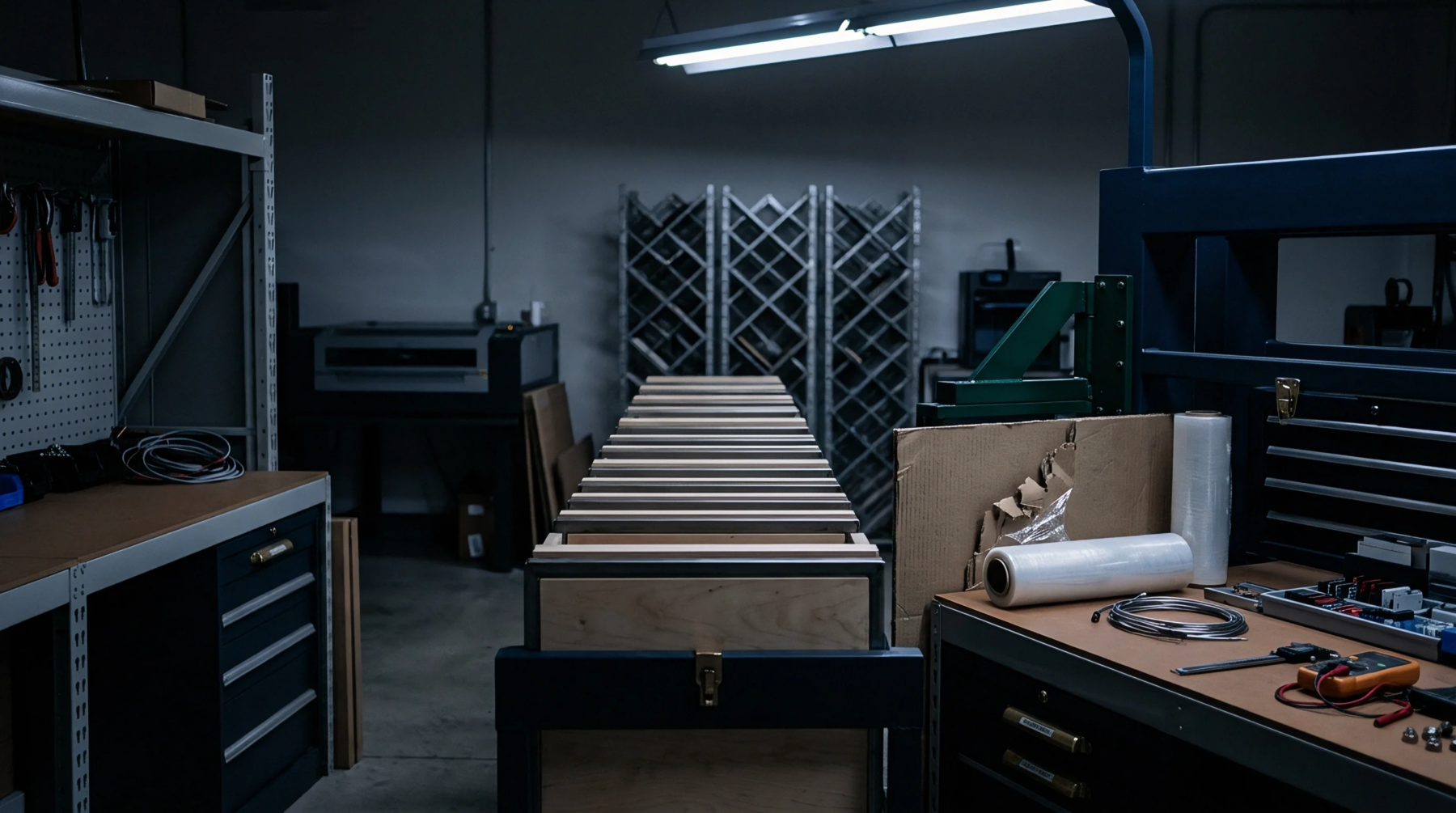
A mechanical testing apparatus facilitates the electrical validation of printed circuit boards by creating simultaneous contact with multiple solder points via an array of spring loaded probes. This bed-of-nails test fixture establishes connectivity across an entire assembly during the final production stage. Manufacturers verify circuit continuity and component values by mapping these physical connections to specific nodes on the board layout.
The architecture relies on precision registration to align internal test points with the probe tips. A vacuum system or pneumatic press forces the circuit board down onto these pins to maintain electrical contact throughout the measurement cycle. Correct alignment ensures the system differentiates between open circuits and legitimate conductive paths on the substrate.
This hardware defines the boundary of verification for high volume electronics production.
Mechanical Alignment
Achieving exact registration demands tolerances often measured in fractions of a millimeter. Every probe aligns with a designated via or pad on the bottom side of the unit under test. Engineers define these targets during the design phase to prevent accidental shorts or damage to delicate components.
Thermal expansion can distort the board material over time and shift the position of test points relative to the fixed grid of probes. Proper guide pins on the frame compensate for such deviations to maintain target accuracy. Small errors in layout translate to inaccurate readings during the screening sequence.
Contact Reliability
Spring force determines the quality of the connection between a probe and its target landing pad. Each spring generates pressure to pierce oxidation or thin layers of contaminants that gather on the metal surfaces during storage. High contact resistance indicates degraded probes or poor surface preparation on the board.
Replacing worn tips restores connectivity when readings become intermittent. Environmental conditions like humidity or dust impact the longevity of the interface and force regular maintenance schedules. The physical state of the pins determines the accuracy of the signal transmission to the diagnostic processor.
Interface Integration
Hardware engineers connect this assembly to the main diagnostic station through a cable harness or a direct interface block. Communication occurs through data acquisition modules that translate analog measurements into digital values for comparison against reference tolerances. Software monitors the output of every node to confirm compliance with the technical specification of the product.
Failed contact creates false reports of defective boards even when the hardware functions correctly. Reliable operation depends on the calibration of the entire chain from the probe tip to the automated evaluation software. Production throughput relies on the efficiency of this connection.
The fixture remains the primary method for isolating manufacturing flaws in dense circuit assemblies.