Meaning
Radiated emission testing procedures evaluate the directional performance and total radiated power of a device under test by rotating it through a complete circle. Performing a turntable measurement in an anechoic chamber ensures that the antenna radiation pattern is captured from every horizontal angle. This procedure is required by international standards to determine the peak effective isotropic radiated power and to identify any hazardous antenna nulls.
Chamber Configuration
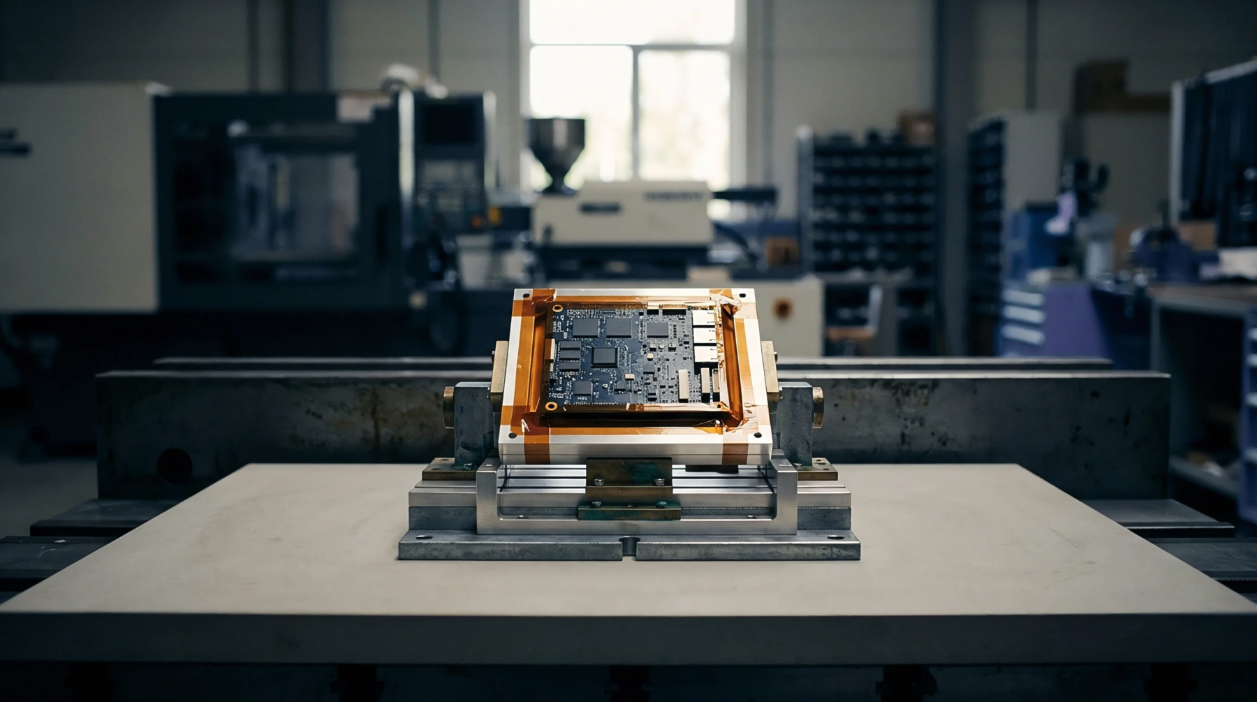
The device under test is secured to a non reflective mast on a rotating platform while a fixed measurement antenna is positioned at a distance of three meters. Continuous rotation allows the receive antenna to capture the signal amplitude at predefined angular increments, such as every five degrees. To prevent reflections from distorting the results, the turntable is fabricated from low permittivity materials like expanded polystyrene.
Multi Axis Rotation
A single horizontal rotation only captures a two dimensional slice of the radiation pattern of the device. To construct a full three dimensional pattern, the device must be rotated on multiple axes or the polarization of the measurement antenna must be switched between horizontal and vertical orientations. This comprehensive sweep reveals the spherical coverage of the antenna, which is critical for smart devices that must connect in any physical orientation.
Analyzing these three dimensional plots allows engineers to optimize the placement of the internal antennas on the circuit board to avoid blocking by the battery or other metal components.
Calibration Step
Before starting the test, a calibration run is performed using a reference antenna with a known gain to calculate the path loss of the chamber. This baseline measurement compensates for cable attenuation, free space path loss, and antenna gain variations across the scanned frequency range. The corrected results provide a highly accurate representation of the radiated performance of the product.