Evaluating Mechanical Strain Limits in Micro Coaxial RF Assemblies
Micro coaxial strain alters 50-ohm impedance, degrades return loss, and spikes radio retransmissions, cutting field battery life and invalidating RF approvals.

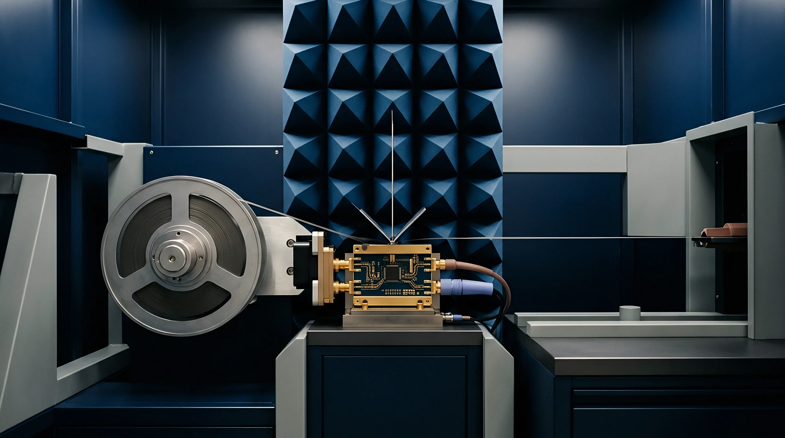
Flexure
Micro coaxial cable assemblies inside compact wireless enclosures experience mechanical stress whenever routing forces exceed the bending stiffness of the miniature coaxial transmission line. Diameters ranging from 0.81 mm down to 0.44 mm utilize thin silver-plated copper-clad steel or alloy center conductors surrounded by fluorinated ethylene propylene or expanded polytetrafluoroethylene dielectrics. When an assembly bends around a tight radius, the outer shield braid slides relative to the inner dielectric.
Tight bend radii compress the dielectric, reducing the distance between the center conductor and the outer shield braid. This geometric shift alters the characteristic impedance from the nominal 50 ohms down to local dips near 35 ohms, creating localized RF energy reflections.
Static and dynamic bending regimes govern physical cable limits differently during device assembly and throughout product operation. Static installation permits tighter radii because the metal braid and shield layers do not suffer ongoing work-hardening. Dynamic applications, such as hinged IoT enclosures or rotating antenna mounts, rapidly introduce fatigue cracks into outer shield strands.
A single severe bend below five times the cable outer diameter causes permanent deformation of the dielectric layer. Micro-cracks in the center conductor elevate conductor resistance, increasing attenuation across 868 MHz, 915 MHz, 2.4 GHz, and 5.8 GHz frequency allocations.
| Cable Diameter Specification | Dielectric Material Type | Minimum Static Bend Radius | Minimum Dynamic Bend Radius | Retention Force Limit | Insertion Loss Shift at 2.4 GHz |
|---|---|---|---|---|---|
| 0.81 mm Micro Coax | Fluorinated Ethylene Propylene | 4.0 mm | 9.0 mm | 4.5 N | +0.15 dB / 100 mm |
| 1.13 mm Micro Coax | Fluorinated Ethylene Propylene | 5.5 mm | 12.0 mm | 8.0 N | +0.12 dB / 100 mm |
| 1.32 mm Micro Coax | Expanded PTFE | 6.0 mm | 15.0 mm | 12.0 N | +0.08 dB / 100 mm |
| 1.37 mm Micro Coax | Fluorinated Ethylene Propylene | 7.0 mm | 18.0 mm | 14.0 N | +0.09 dB / 100 mm |
Axial tension on micro coaxial connectors poses an acute risk to surface-mount landing pads on cellular and Wi-Fi mainboards. Ultra-small miniature RF connectors, including U.FL, W.FL, and MHF series, rely on snap-on friction retention rings to hold mating shells together. Pulling a micro coaxial cable at an angle relative to the socket centerline concentrates mechanical force onto one side of the receptacle solder pads.
Shear stress peels the copper trace directly off the printed circuit board substrate, severing ground return paths long before the metallic connector shell mechanically separates. Copper traces lift easily.
Bending micro coaxial cable below five times its outer diameter permanently crushes the internal dielectric and alters characteristic impedance.
Cellular modules operating across sub-GHz bands suffer immediate degradation when cable strain alters ground path continuity between the radio board and the antenna ground plane. A 1 dB increase in RF insertion loss cuts transmit power delivered to the antenna by over twenty percent, which degrades sensitivity margins on long-range links. Sub-GHz LoRaWAN gateways using 868 MHz or 915 MHz channels lose up to two kilometers of line-of-sight range when cable strain introduces impedance mismatches near the connector interface.
Mechanical stress at the assembly stage degrades field reliability across all deployable radio allocations.


Discontinuity
Impedance mismatches caused by cable strain change signal propagation characteristics along micro coaxial assemblies. RF energy traveling down a distorted transmission line encounters impedance steps that reflect a portion of the signal back toward the transmitter power amplifier. Return loss measures this reflected power; a baseline baseline return loss of 20 dB can rapidly collapse to 8 dB under structural strain.
The resulting voltage standing wave ratio increases from an acceptable 1.2:1 up to 2.3:1 or worse. Power amplifier stages inside LTE-M, NB-IoT, or Wi-Fi 6E radios must draw extra supply current to compensate for reflected power losses to maintain output target levels.

What Mechanical Thresholds Trigger Unrecoverable RF Loss?
Dielectric distortion exceeding ten percent of cross-sectional thickness creates measurable high-frequency phase shifts. At higher frequencies like 5.8 GHz and the 6 GHz Wi-Fi 7 band, tiny physical disruptions measureable in fractions of a millimeter match a significant portion of the guided RF wavelength. Signal phase shifts destabilize beamforming antenna arrays and multi-antenna MIMO systems, degrading signal-to-noise ratios at the receiver demodulator.
Phase instability degrades throughput faster than simple attenuation because phase noise ruins complex quadrature amplitude modulation schemes.
- Conductor displacement occurs when tight cable bends force the center pin off the electrical axis, altering transmission line inductance per unit length.
- Braid strand fatigue happens after repetitive dynamic flexing breaks individual outer shield wires, reducing shield coverage percentage and elevating electromagnetic interference radiation.
- Connector interface canting occurs when side loads lift one side of the snap-on micro connector socket, creating a capacitive air gap across the signal pin.
- Trace micro-cracking develops under solder joints subject to unmitigated cable tension, increasing DC resistance and generating intermittent RF attenuation spikes.
Energy budgets for battery-powered wireless devices degrade when mechanical strain forces radios into aggressive retransmission regimes. Cellular LTE-M devices operating under poor return loss conditions trigger module power amplifier backoff protections or initiate repeated uplink transmissions to reach base stations. Higher packet error rates keep the cellular modem awake longer during transmission windows, turning microampere-level sleep designs into milliampere-draining burdens.
Battery depletion occurs prematurely.
A voltage standing wave ratio rising above 2.0:1 forces cellular modems to retransmit data packets and drains field batteries ahead of schedule.
When cable tension forces the center contact pin within a micro connector out of alignment, the contact spring force declines rapidly. Micro-arcing can occur under high-power transmit bursts, such as +30 dBm pulses generated by GSM or high-power sub-GHz transmitters. Oxidation forms over the contact surface, producing non-linear junction behavior that generates intermodulation distortion products inside adjacent frequency bands.
Static installation layouts require cable bend radii to stay above conservative safety thresholds to prevent signal degradation over product operational lifetimes.

Clamp
Strain relief mechanisms protect delicate micro coaxial solder joints and miniature RF connectors from external mechanical tension. Raw miniature snap-on connectors offer minimal retention force; standard U.FL connectors offer approximately 10 N of initial unmating force, which decreases to 3 N after five mechanical mating cycles. Micro-miniature MHF4 and W.FL series yield even lower retention values, often dislodging under light assembly vibration.
Mechanical anchor points must take up external stress before tensile loads reach the connector housing.
Adhesive potting compounds, mechanical retaining brackets, and specialized routing clips provide structural strain isolation when correctly applied. UV-curable epoxies and room-temperature vulcanizing silicone compounds are frequently deposited directly over mated connector shells to lock them to the printed circuit board. Liquid adhesives detune nearby microstrip trace impedances if their dielectric constant differs sharply from air.
Thermal hot-melt adhesives expand and contract across industrial temperature ranges, pushing connectors away from sockets during thermal cycling tests between minus forty and plus eighty-five degrees Celsius.
- Position the micro coaxial cable flat along the printed circuit board routing channel without applying axial twist to the cable body.
- Snap the miniature connector vertically into the board socket until the tactile retention detent fully engages.
- Apply a single controlled dot of low-outgassing structural epoxy over the mated connector junction and adjacent board substrate.
- Pass the cable through a mechanical strain-relief routing clip located fifteen millimeters from the connector edge.
- Verify RF insertion loss across the active radio bands using a continuous vector network analyzer frequency sweep.
Mechanical retention clips stamped from stainless steel provide superior thermal and mechanical stability compared to chemical adhesives. Retention clips clamp down over the connector top shell and anchor directly to nearby surface-mount board pads or enclosure features. Stainless clips absorb cable tugging forces, shielding PCB solder joints from shear stress during field maintenance.
| Strain Relief Method | Retention Force Addition | RF Detuning Impact | Rework Ability | Thermal Stability (-40°C to +85°C) |
|---|---|---|---|---|
| Structural UV Epoxy | +25 N | Moderate (-0.3 dB shift) | Poor (Requires heat gun) | High stability |
| RTV Silicone Gel | +12 N | Low (-0.1 dB shift) | Fair (Peels away cleanly) | Moderate (Temperature soft) |
| Stamped Steel Clip | +35 N | Negligible (Zero contact) | Excellent (Removable spring) | High stability |
| Recessed Channel Guide | +8 N | Zero detuning | Excellent (Slide routing) | High stability |
Cable suppliers frequently attribute connector unseating and center-pin failure during vibration testing to user installation errors rather than inadequate strain relief design.

Fixture
Quantifying mechanical strain limits in micro coaxial RF assemblies requires dynamic mechanical test fixtures combined with high-frequency RF monitoring equipment. A primary test setup pairs an automated linear or rotary flexure fixture with a vector network analyzer. Cable samples undergo thousands of controlled bending cycles while the analyzer continuously records transmission parameter S21 and reflection parameter S11.
Sudden spikes in return loss during a bending cycle indicate transient shield separation or intermittent center conductor fracture.
Time domain reflectometry allows test engineers to pinpoint physical strain locations along a cable harness down to single-millimeter resolution. Signal reflections mark exact points where dielectric crushing, outer shield necking, or conductor stretching alters local impedance. Testing proves that pulling cables over sharp enclosure metal edges causes immediate dielectric cold flow, shifting localized impedance down to 40 ohms within 500 mechanical cycles.
Consider a practical battery life calculation for an industrial IoT sensor operating on a single 19 Ah lithium thionyl chloride cell. The device uses an LTE-M cellular module transmitting at +23 dBm output power into an undamaged 1.13 mm micro coaxial cable with 0.4 dB insertion loss. Under normal conditions, the radio draws 220 mA peak current during a 2-second uplink burst once per hour, achieving a 10-year field operational life.
If cable strain degrades return loss from 18 dB down to 6 dB, over 25 percent of transmit RF power reflects back into the module PA. To maintain link registration with the cell tower under carrier link quality mandates, the modem increases transmit duration through retransmissions, elevating average active current draw to 380 mA for 6 seconds per packet. This mechanical strain failure degrades calculated battery service life from 10 years down to 2.8 years without generating an explicit hardware error code.
Standard specification clauses governing miniature coaxial assemblies dictate zero conductor movement under three-axis tensile loads up to ten Newtons.
What safety margin must an RF engineer integrate into cable strain specifications to account for vibration profiles in industrial applications?

Logistics
Mechanical strain in micro coaxial assemblies affects global regulatory approvals, inventory management, and landed product costs. Radio modules receive modular certifications based on specific antenna and cable assembly configurations tested in compliance laboratories. Substituting a micro coaxial cable with an unverified alternative or altering cable routing so severely that mechanical strain causes spurious emissions invalidates FCC, CE, and ISED regulatory filings.
Non-compliant harmonic radiation occurs when broken outer shield braids leak RF energy into adjacent metallic enclosure structures, turning internal wiring into unintentional radiator elements.
Selecting cable specifications for volume manufacturing involves balancing mechanical durability against unit pricing. Standard 0.81 mm micro coaxial assemblies cost less and fit into compact enclosures, but exhibit higher assembly defect rates if operators pull cables during installation. Larger 1.37 mm micro coax cables offer superior strain tolerance and lower insertion loss, but demand larger bend radii that increase enclosure dimensions.
Sourcing teams analyze total landed cost by factoring field warranty returns into initial component selection.
- Minimum static bend radius metrics must be specified explicitly on procurement drawings to prevent assembly floor technicians from over-bending harness runs.
- Connector mating cycle ceilings must be tracked in factory work instructions to ensure worn test fixtures do not degrade production connector pins.
- Strain relief clip placement must be standardized across mechanical assembly documentation to guarantee strain isolation before PCB soldering.
- Traceability batch codes must be marked on micro coaxial cable lots to isolate dielectric degradation issues back to raw material suppliers.
Procuring pre-assembled micro coaxial jumper leads with factory-molded strain relief boots reduces manual assembly errors on high-volume production lines. Standardized testing protocols ensure incoming cable lots comply with insertion loss and VSWR specifications before boards enter final enclosure assembly steps. Cable selections affect radio performance, regulatory compliance, and long-term field maintenance costs across global markets.