Cellular IoT Receiver Sensitivity Testing Standards
Cellular IoT sensitivity testing requires validating conductive limits under full transmit power and measuring radiated TIS across 3D spatial grids.

Signal
Receiver performance in Category M1 and Narrowband IoT devices is anchored to minimum input level criteria defined in 3GPP TS 36.101 and TS 36.521-1. The baseline metric, static reference sensitivity, specifies the lowest RF input power level at the module antenna port where the receiver achieves a 95 percent throughput target. This throughput target corresponds to a frame error rate or Block Error Rate ceiling of 5 percent under static propagation conditions with no multipath impairment.
For LTE-M (Cat-M1), operating across a 1.4 MHz channel bandwidth with 6 resource blocks, standard reference sensitivity ranges from -103 dBm to -108 dBm depending on the operating band. For NB-IoT (Cat-NB1/NB2), occupying a single 200 kHz carrier (180 kHz transmission bandwidth), reference sensitivity limits are significantly lower, specified between -114 dBm and -117.5 dBm at the receiver input port.

Standardized Reference Sensitivity Baselines
Testing protocols mandate strict signal conditions to establish compliant baseline sensitivity measurements. RF signal generators deliver a quadrature phase-shift keying (QPSK) modulated downlink carrier containing a fully allocated transport block. Thermal noise sets the physical baseline floor, calculated as:
P_noise = k T B
Where k is Boltzmann’s constant (1.38 x 10^-23 J/K), T is system temperature in Kelvin (290 K standard reference), and B is channel noise bandwidth. Across an NB-IoT 180 kHz noise bandwidth, the thermal floor equals -121.4 dBm. A module operating with a 4 dB internal receiver noise figure and requiring a -2 dB Signal-to-Noise Ratio (SNR) for QPSK demodulation yields an absolute sensitivity limit of -119.4 dBm.
The table below summarizes minimum 3GPP conductive reference sensitivity requirements across primary sub-GHz and mid-band allocations used in international cellular deployments.
| Protocol Standard | 3GPP Band Allocation | Nominal Bandwidth | Modulation Scheme | 3GPP Min Sensitivity | Field Benchmark |
|---|---|---|---|---|---|
| LTE Cat-M1 (TS 36.101) | Band 20 (800 MHz) | 1.4 MHz (6 RB) | QPSK | -104.0 dBm | -107.5 dBm |
| LTE Cat-M1 (TS 36.101) | Band 4 (1700/2100 MHz) | 1.4 MHz (6 RB) | QPSK | -103.0 dBm | -106.0 dBm |
| LTE Cat-NB1 (TS 36.101) | Band 8 (900 MHz) | 200 kHz (1 RB) | QPSK / BPSK | -114.0 dBm | -117.0 dBm |
| LTE Cat-NB2 (TS 36.101) | Band 28 (700 MHz) | 200 kHz (1 RB) | QPSK / BPSK | -115.0 dBm | -118.5 dBm |

Block Error Rate Ceilings in Conductive Channel Verification
Measuring conductive sensitivity requires an automated RF test set capable of executing Hybrid Automatic Repeat Request (HARQ) loopback scenarios. The RF generator transmits a sequence of standardized transport block sizes while monitoring receiver acknowledgments (ACK/NACK responses). RF input power decreases in discrete steps, typically 0.5 dB increments, until the HARQ Block Error Rate exceeds the 5 percent ceiling.
Settling time at each power step ensures statistical confidence, demanding a minimum of 1000 transport blocks per test point. RF cabling losses between the tester port and the module U.FL or mmCX connector require precision calibration using a vector network analyzer. An uncalibrated 0.8 dB insertion loss in the RF cable shifts an actual receiver sensitivity of -116.2 dBm to a recorded datasheet figure of -117.0 dBm, masking hardware marginality.
- Connect the module antenna port directly to the RF test set output using low-loss double-shielded coaxial cables.
- Execute a frequency-response sweep across the test lead to quantify insertion loss at target carrier center frequencies.
- Establish a active radio resource control connection with the base station simulator at a nominal downlink power level of -70 dBm.
- Configure the tester to command the device into maximum transmit power output to simulate worst-case internal coupling conditions.
- Attenuate the downlink carrier power in 0.5 dB steps while calculating throughput across a 1000-block window until BLER exceeds 5 percent.
3GPP TS 36.521-1 Section 7.3 specifies that reference sensitivity tests land on an exact 5 percent block error rate ceiling under maximum uplink transmit power conditions.
Commercial module vendors often quote sensitivity under passive receiver conditions where the uplink transmitter remains idle. Operating the receiver while the internal power amplifier transmits at +23 dBm reveals self-heating effects and RF coupling that degrade real-world sensitivity by 2 dB to 6 dB. Clause 7.3.5 of 3GPP TS 36.521-1 binds receiver qualification directly to simultaneous transmit activity, compelling testing engineers to verify sensitivity limits under full uplink duty cycles.


Noise
Internal hardware noise represents the primary cause of degraded sensitivity in integrated IoT products. When a cellular module is placed on a main system motherboard alongside power conversion circuits, microcontrollers, display interfaces, and high-speed serial buses, radiative and conductive emissions degrade receiver performance. This phenomenon, known as desensitization or desense, elevates the effective noise floor of the receiver architecture above its theoretical thermal limit.

Board-Level Electromagnetic Desensitization Mechanisms
Switching DC-DC regulators operating between 500 kHz and 3 MHz generate wideband harmonic energy extending directly into sub-GHz cellular receive bands. A Buck converter operating at 1.2 MHz produces odd harmonics that fall into Band 8 (900 MHz) and Band 20 (800 MHz) receive channels. Near-field magnetic coupling from unshielded inductors directly injects noise currents into the cellular receiver RF front-end trace or antenna feedpoint.
High-speed digital interfaces, including SPI buses, MIPI display lines, and USB data tracks, radiate broadband spectrum spikes. A single 24 MHz clock trace with a 1 ns rise time generates harmonic spikes every 24 MHz across the entire 700 MHz to 2200 MHz spectrum. Receiver desense manifests as a drop in effective sensitivity from a module baseline of -117 dBm down to -102 dBm on an unshielded board.
A 3 dB elevation in the receiver front-end noise floor reduces cellular coverage area by exactly 50 percent.
- Switching Regulator Harmonics inject broadband spurious noise directly into the receiver low-noise amplifier through shared power planes and spatial coupling.
- High-Speed Bus Radiation creates harmonic spectrum spikes that land inside cellular receive band channels, forcing channel-dependent sensitivity drops.
- Ground Plane Current Loops introduce common-mode voltage offsets between the module RF ground pins and the main board ground plane, detuning the antenna match.
- Processor Clock Leakage radiates narrowband spectral lines that desensitize specific channel numbers while leaving adjacent channels unaffected.

Coexistence Losses across GNSS and Cellular Front-Ends
Devices housing simultaneous cellular and GNSS capabilities face severe front-end isolation challenges. Cellular transmit power reaching +23 dBm (200 mW) at 824-849 MHz (Band 5 uplink) generates second harmonic emissions at 1648-1698 MHz. This second harmonic overlaps directly with the GPS L1 band at 1575.42 MHz and the GLONASS L1 band at 1602 MHz.
High transmitter power swamps the GNSS receiver low-noise amplifier, driving the stage into non-linear gain compression. Intermodulation distortion (IMD) between cellular carrier tones and nearby Wi-Fi or Bluetooth transmissions similarly produces third-order intermodulation products (IMD3) landing inside cellular receive bands. Integrating high-rejection surface acoustic wave (SAW) or thin-film bulk acoustic resonator (FBAR) filters between the antenna feed and the LNA preserves receiver gain at the expense of 1.2 dB to 2.5 dB front-end insertion loss.
Failure to isolate noise sources during board layout forces costly board spins late in the qualification cycle. Redesigning ground planes, adding metallic shielding cans over power stages, and incorporating inline RF notch filters add physical BOM costs while delaying carrier certification schedules.


Rig
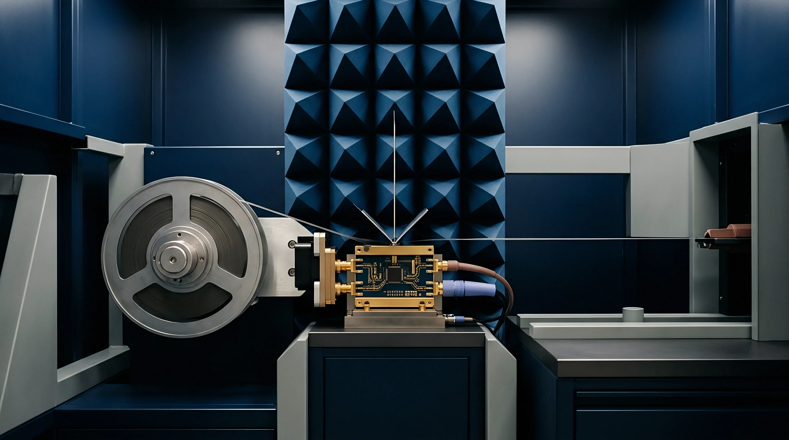
Evaluation of receiver sensitivity split into two distinct testing methodologies: conductive bench evaluation and radiated Over-The-Air testing. Conductive measurements evaluate module RF performance via direct coaxial connection, bypassing antenna characteristics. Radiated testing evaluates the fully assembled end-device inside an anechoic chamber, capturing the cumulative impact of antenna efficiency, gain pattern distortion, body losses, and enclosure dielectric loading.

Where Does Conductive Measurement Fail to Predict Radiated Performance?
Conductive bench data provides an optimistic baseline that fails to reflect real-world performance. A module measuring -116 dBm conductive sensitivity inside a shielded box frequently exhibits a Total Isotropic Sensitivity (TIS) of only -104 dBm when tested as a completed product. Antenna radiation efficiency represents the dominant loss factor.
Compact IoT enclosures often restrict antenna dimensions below optimal quarter-wavelength physical boundaries. A sub-GHz antenna forced into a 30 mm enclosure footprint yields radiation efficiencies between 15 percent and 35 percent (-8.2 dB to -4.5 dB insertion loss). Dielectric loading from polycarbonate or ABS plastic housings further detunes the antenna resonant frequency, shifting matching networks away from maximum power transfer conditions.
CTIA Test Plan for Wireless Device Over-The-Air Performance defines standardized procedures for measuring TIS. The device hangs inside a fully anechoic chamber on a two-axis dielectric positioner. A calibrated measurement antenna mounted on the chamber wall records spherical receive power across 15-degree spatial steps.
Total Isotropic Sensitivity is calculated via mathematical integration over the full 3D sphere:
TIS = 4 PI / ( integral_0^PI integral_0^(2 PI) sin(theta) d-phi d-theta )
Where S_theta and S_phi represent receiver sensitivity measured at specific polarization angles and spatial coordinates. Evaluating TIS requires measuring sensitivity at dozens of points across the spherical grid, making full OTA execution time-intensive, typically requiring 2 to 4 hours per frequency channel.
| Test Methodology | Primary Standard | Measured Parameter | Execution Environment | Primary Measurement Limitation |
|---|---|---|---|---|
| Direct Conductive | 3GPP TS 36.521-1 | Static Reference Sensitivity | RF Shield Box / Coaxial Cable | Ignores antenna losses and spatial detuning |
| Spherical OTA TIS | CTIA OTA Test Plan | Total Isotropic Sensitivity | Anechoic Chamber + 3D Positioner | High test chamber cost and long execution time |
| Phantom-Loaded Radiated | CTIA / Operator Custom | Loaded Radiated Sensitivity | Anechoic Chamber with Fluid Phantom | Difficult reproducibility across test labs |
| Reverberation Chamber | IEC 61000-4-21 | Isotropic Radiated Sensitivity | Multipath Stirred Metal Chamber | Lacks directional spatial gain resolution |

Chamber Geometry and Spatial Sampling Criteria
Spatial sampling resolution dictates test accuracy within anechoic chambers. CTIA guidelines mandate 15-degree spatial grids for frequencies below 1 GHz and 10-degree grids for mid-band cellular channels. Incorrect positioning of internal batteries, sensors, or wiring harnesses distorts the 3D radiation pattern, creating deep spatial nulls where receiver sensitivity degrades by 15 dB to 25 dB in specific orientations.
Devices placed near metallic mounting structures or human body mass experience near-field loading. CTIA certification tests specify standard head, hand, and torso fluid-filled phantoms to quantify human proximity loss, which typically introduces 3 dB to 12 dB of additional signal attenuation.
Module vendors frequently claim their hardware achieves superior receiver sensitivity based solely on conductive test sheets. Standard supplier responses downplay radiated losses by assuming an idealized 0 dBi antenna gain, passing the burden of antenna tuning and board desense mitigation to the device integrator.


Fade
Static receiver sensitivity measurements fail to capture the dynamic channel impairments encountered in field deployments. Mobile cellular nodes, asset trackers, and vehicle gateways experience rapid signal fluctuations caused by environmental multipath reflections, terrain shadowing, and movement-induced Doppler shifts. 3GPP defines dynamic propagation models to evaluate receiver performance under non-line-of-sight conditions.

Multipath Propagation Channels and Doppler Profiles
Testing receiver sensitivity under realistic field conditions requires channel emulators capable of applying fading profiles defined in 3GPP TS 36.101. Standard profiles include Extended Pedestrian A (EPA), Extended Medium Urban (EMU), and Extended Typical Urban (ETU). These profiles simulate environmental delay spreads ranging from 45 nanoseconds in rural settings up to 5 microseconds in dense urban canyons.
Doppler frequency shifts are applied based on relative vehicle speeds:
fd = (v / c) f0
Where v is device velocity, c is light speed, and f0 is carrier frequency. A vehicle moving at 120 km/h on a 900 MHz link incurs a Doppler shift of 100 Hz. Fast fading causes signal power drops exceeding 20 dB across millisecond intervals. Receiver equalizer algorithms must dynamically track channel variations to maintain coherent demodulation without losing frame synchronization.
The table below outlines standard 3GPP fading profiles used to evaluate LTE-M and NB-IoT receiver tracking capabilities under physical movement.
| Fading Channel Profile | Delay Spread RMS | Max Doppler Frequency | Simulated Environment | Required SNR Offset vs Static |
|---|---|---|---|---|
| Extended Pedestrian A (EPA 5Hz) | 45 ns | 5 Hz (3 km/h @ 1.8 GHz) | Indoor / Slow Walking | +3.5 dB |
| Extended Typical Urban (ETU 70Hz) | 990 ns | 70 Hz (42 km/h @ 1.8 GHz) | Suburban Driving | +7.2 dB |
| High Speed Train (HST 300Hz) | 150 ns | 300 Hz (180 km/h @ 1.8 GHz) | Express Railway | +11.0 dB |

Repetition Scaling under Extended Coverage Enhancement
Cellular IoT standards introduce Coverage Enhancement (CE) mechanisms to maintain link connectivity deep inside buildings, basements, and underground vaults. LTE-M defines CE Mode A (modest coverage extension) and CE Mode B (deep coverage extension). NB-IoT implements repetition modes scaling up to 128 repetitions on the downlink and uplink.
Through repetition, the base station transmits identical data transport blocks multiple times. The receiver combines energy across repeated blocks using soft-decision Maximum Ratio Combining (MRC), lowering the effective thermal noise floor proportionally to the repetition count:
Gain_SNR = 10 log10(N_repetitions)
Executing 128 repetitions yields a theoretical SNR improvement of 21 dB, extending NB-IoT operational receiver sensitivity from -117 dBm down to -138 dBm. This coverage extension allows sub-GHz signals to penetrate up to two reinforced concrete basement walls or deep utility pits.
NB-IoT repetition processing lowers the theoretical noise floor by 21 dB at the expense of a 128-fold increase in frame transmission time.
Repetition processing trades bandwidth and operational latency directly for link sensitivity. Increasing repetitions reduces data throughput from 100 kbps down to a few hundred bits per second, while holding the device receiver active for seconds per message payload. Antenna efficiency degrades faster in deep basement locations due to near-field metal coupling than path loss alone accounts for.


Budget
Link budget calculations translate receiver sensitivity limits into operational coverage radiuses and battery service life projections. Designing cellular hardware for smart metering, industrial monitoring, or logistics tracking demands accounting for every decibel of gain and loss between the base station antenna and the module receiver front-end.

Calculated Link Margins for Indoor and Subterranean Nodes
Maximum Allowable Path Loss (MAPL) defines the total loss a radio signal can endure while maintaining acceptable throughput. MAPL is calculated as:
MAPL = P_tx + G_tx + G_rx – P_sensitivity – L_margins
Where P_tx is base station transmit power, G_tx is base station antenna gain, G_rx is device antenna gain, P_sensitivity is receiver sensitivity, and L_margins includes shadow fading and penetration losses. Sub-GHz bands offer superior propagation efficiency over mid-band frequencies, providing lower attenuation through structural obstacles.
The following plain numbered sequence details the mathematical steps for deriving MAPL for an NB-IoT water meter installed inside a subterranean concrete vault.
- Establish base station transmit power at +46 dBm across a standard cellular sector antenna.
- Add base station sector antenna gain of +15 dBi to derive Effective Isotropic Radiated Power (EIRP) of +61 dBm.
- Apply device antenna total radiated gain including enclosure detuning losses, setting G_rx to -6 dBi.
- Set target receiver sensitivity under 32 repetitions to -132 dBm.
- Calculate raw unadjusted link budget limit: +61 dBm – (-6 dBi) + 132 dBm = 187 dB.
- Subtract structural concrete penetration loss (18 dB) and soil attenuation (12 dB) for a subterranean installation.
- Subtract a 10 dB log-normal shadow fading margin to guarantee 95 percent location reliability.
- Derive final usable Maximum Allowable Path Loss of 147 dB for geographical cell radius coverage calculations.

Trade-Offs between Energy Draw and Received Power Thresholds
Receiver sensitivity directly dictates power consumption profiles in battery-operated IoT products. When a device operates near its maximum sensitivity limit (-130 dBm in CE Mode B), the radio receiver remains powered on for extended durations to perform soft combining across repeated frames. A single 100-byte telemetry payload transmitted under clear line-of-sight conditions requires 120 milliseconds of active airtime, drawing 45 mA at 3.6 V. Under deep coverage conditions requiring 64 repetitions, airtime scales to 7.6 seconds, increasing total energy consumption per message by a factor of 60.
| Operating Mode | Signal Input Level | Repetition Count | Active Airtime | Energy Per Message | Estimated Battery Life |
|---|---|---|---|---|---|
| Cat-M1 CE Mode A | -95 dBm | 1 | 45 ms | 0.015 mAh | 10.2 Years |
| Cat-M1 CE Mode A | -108 dBm | 8 | 360 ms | 0.120 mAh | 7.8 Years |
| Cat-NB1 Standard | -105 dBm | 1 | 120 ms | 0.040 mAh | 9.5 Years |
| Cat-NB1 CE Mode B | -128 dBm | 64 | 7680 ms | 2.560 mAh | 1.4 Years |
Designing hardware to operate reliably at sensitivity limits without sacrificing battery longevity requires rigorous system-level energy modeling. How much field battery degradation occurs when network operators reconfigure cell sector power levels or reduce repetitions to manage network congestion?


Audit
Ensuring cellular IoT hardware meets global regulatory standards and carrier requirements demands formal verification files. Sourcing teams and RF engineering leads review test documentation to verify that production units maintain compliance under volume manufacturing conditions.

Certification Dossiers and Operator Acceptance Limits
Prior to commercial network connection, cellular devices obtain certification through regional regulatory bodies (FCC, RED, ISED) and industry consortia (PTCRB, GCF). Regulatory testing focuses primarily on transmitter spurious emissions and electromagnetic compatibility (EMC). Industry certification bodies enforce strict receiver sensitivity limits through mandatory 3GPP conformance testing.
Mobile Network Operators (MNOs) enforce independent requirement specifications exceeding standard 3GPP thresholds. Tier-1 operators in North America and Europe mandate TIS performance up to 3 dB stricter than base PTCRB baselines to minimize network capacity loss caused by marginal user equipment.
Procurement dossiers must contain certified lab test reports generated by ISO/IEC 17025 accredited facilities. Reports include conductive reference sensitivity tables across all supported LTE bands, radiated TIS plots, and desense matrices mapping clock harmonic interference across channel frequencies.

Production Batch Tolerance and Verification Intervals
Sensitivity verified on a single engineering prototype guarantees little about high-volume production output. Silicon lot variations, passive component tolerances, surface-mount placement errors, and antenna connector soldering variations introduce unit-to-unit performance spreads. Statistical process control requires testing sample units from every manufacturing lot using automated production test benches.
Production line testing utilizes simplified RF test sets executing fast conductive packet-error-rate sweeps. Tolerances typically allow a +/- 1.5 dB window around the calibrated baseline figure. Units failing this tolerance window are rejected to prevent shipping devices susceptible to field dropouts.
Factory screening verifies receiver functionality across temperature extremes (-40°C to +85°C), catching thermal drift in crystal oscillators that degrades carrier frequency tracking and receiver sensitivity under extreme weather conditions. Maintaining complete traceability between module batch serial numbers and RF test logs enables rapid isolation of field failures during warranty investigations.