Closed-Loop Impedance Tuner Dissipation during Severe Dynamic Hand Loading Detuning
Dynamic hand loading increases tuner insertion loss and circulating current, converting power amplifier output into heat under severe mismatch states.


Flesh
Proximity to human tissue alters the local permittivity around an embedded antenna and causes substantial dielectric absorption. In free space, antenna impedance closely matches the power amplifier’s fifty-ohm output stage. Placing fingers or a palm over the radiator pulls the resonant frequency lower and shifts input impedance far across the Smith chart.
Instead of radiating as electromagnetic waves, RF energy couples into biological tissue, converting high-frequency currents into thermal loss within skin and subcutaneous layers.

Dielectric Loading Mechanics in Handheld Transceivers
At two point four gigahertz, the complex permittivity of biological tissue immediately detunes resonant structures. High real permittivity shortens the effective wavelength near the antenna trace, dragging natural resonance down by hundreds of megahertz, while the imaginary permittivity component introduces conductive loss. When a hand fully covers the antenna, the standing wave ratio degrades from a nominal one point five to one to beyond eight to one.
Hand dielectric loading pulls antenna input impedance from fifty ohms to severe mismatch vectors exceeding an eight to one standing wave ratio.
Antenna mismatch cuts radiated power through reflection and resistive absorption, sending transmit signals back toward the front-end module. The returning wave interacts with the forward signal, establishing high voltage or current peaks along the transmission feed line depending on the load reflection phase angle.

Impedance Excursions across Hand Positions
Return loss degrades rapidly when an operational grip covers the edge of the ground plane. A two-finger pinch on a chassis corner creates a markedly different impedance trajectory than a full-palm cupped grip, with dielectric loading altering both real resistance and imaginary reactance at the antenna port.
| Grip Configuration | Resistance (Ohms) | Reactance (Ohms) | VSWR | Dielectric Absorption Loss (dB) |
|---|---|---|---|---|
| Free Space Reference | 48.5 | +1.2 | 1.04:1 | 0.00 |
| Two-Finger Pinch | 22.1 | -34.8 | 3.12:1 | 1.85 |
| Tight Palm Grip | 8.4 | +42.6 | 7.85:1 | 4.30 |
| Cupped Hand Enclosure | 5.2 | -12.1 | 10.15:1 | 6.10 |
Severe detuning degrades radiated link efficiency. Designing matching circuits without accounting for severe hand dissipation leads to thermal throttling and premature battery depletion in handheld terminals.


Loop
Automated impedance correction systems evaluate phase and magnitude variations from a directional coupler to update matching states. The closed-loop controller compares the complex reflection coefficient against an internal tuning objective, signaling variable capacitor banks to realign the RF front end toward fifty ohms. When hand loading shifts dynamically during speech or data entry, the control algorithm must update match settings within microseconds to prevent power amplifier mismatch stress.

Control Algorithm Latency and Convergence Trajectories
Real-time optimization steps execute within microsecond intervals to track sudden reflection changes. Convergence speed determines how long the transmitter operates into an unmatched load state. Gradient descent strategies risk landing in local loss minima when dielectric loading shifts faster than the feedback sample rate, while phase detector offsets distort phase estimation and lengthen the iterative search path.
Closed-loop impedance tuners require feedback sampling cycles under fifty microseconds to keep pace with dynamic hand movement detuning.

Why Does High Reflection Rate Degrade Loop Tracking?
Severe reflection spikes confuse magnitude detectors and push adaptive tuning algorithms into sub-optimal search spaces. High standing wave amplitudes distort coupler output linear range, and phase measurement accuracy collapses once return loss drops below three decibels. The tuning system hunting loop oscillates between extreme capacitive states while searching for match stability.
- Detector Saturation blinds phase sensing circuitry during extreme standing wave peaks, delaying corrective tuning updates.
- Search Algorithm Oscillation cycles switch settings repeatedly when multidimensional gradient steps overshoot target impedance.
- Coupler Directivity Degradation skews reflection magnitude calculations when load phase shifts rapidly across Smith chart boundaries.
- Look-up Table Mismatch applies incorrect static switch settings during uncalibrated dynamic hand grip states.
Transient response instability originates from unexpected antenna ground plane geometries rather than control loop latency.


Coil
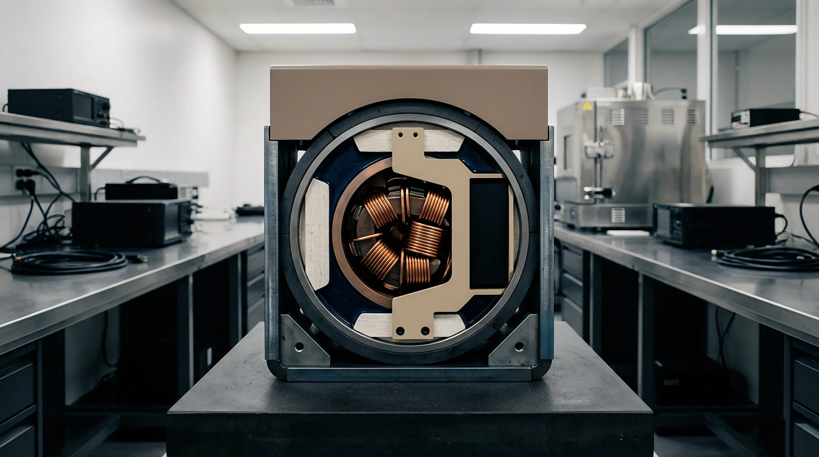
High quality-factor inductors and switched capacitor matrices form the internal matching circuit topology. Because every reactive element carries internal resistance, dynamic detuning drives current densities beyond nominal baselines and converts transmitter energy into internal heating rather than forward radiation.

Circulating Current Amplification under Severe Mismatch
Standing waves inside matching circuits force reactive energy into inductive branches. In a discrete pi-matching array compensating for an eight to one load standing wave ratio at two watts transmit power into a nominal fifty-ohm reference, peak current through the series inductor remains near two hundred milliamperes under matched conditions. When hand loading pulls the load impedance down to five ohms real, circulating current inside the matching inductor multiplies by more than three times.
Calculated ohmic loss follows the square of circulating current multiplied by equivalent series resistance. An inductor carrying a zero point five ohm series resistance dissipates zero point zero two watts under matched load conditions. Under severe five-ohm mismatch, circulating current jumps to six hundred and thirty milliamperes, driving dissipation in that single inductive component to zero point two watts.
Higher network Q factors increase reactive energy circulating through internal elements, raising tuner dissipation under mismatched conditions.

Ohmic Losses in Switched Capacitor Matrices
Series resistance across silicon switch channels converts active RF excitation into heat. Digital tunable capacitors use solid-state switches to engage binary-weighted capacitor banks, with each closed switch branch adding active channel resistance. When SWR exceeds eight, high reactive currents flowing through ON-state switches produce heavy resistive power loss.
Evaluating tuner performance requires inspecting component selection criteria across internal building blocks.
- Inductor Series Resistance limits overall circuit efficiency by converting high reactive circulating currents into localized heat.
- Capacitor Switch Channel Resistance generates power dissipation inside digital tunable capacitor integrated circuits during high RF voltage swings.
- Substrate Parasitic Conductance leaks high-frequency current into semiconductor silicon substrates during severe voltage standing wave conditions.
- Interconnect Trace Inductance distorts phase tuning bounds and lowers element quality factors across higher operational frequency bands.
Elevated circuit quality factors increase reactive energy circulating through internal elements, raising tuner dissipation under mismatched conditions.

Stress
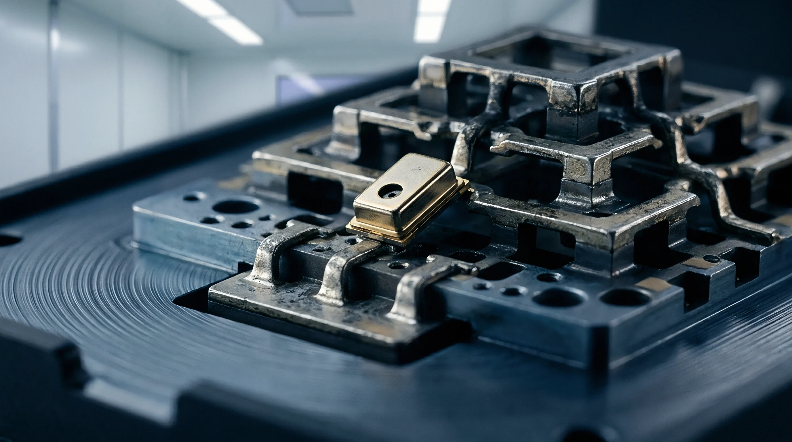
Peak RF voltage node locations shift dynamically as antenna load impedance traverses the Smith chart. Extreme mismatch conditions produce high voltage standing waves inside tuner circuits, subjecting switched capacitor arrays to peak terminal voltages far higher than standard supply rails. Overvoltage stress degrades thin-film dielectric layers inside RF switches, altering switch channel conductivity over time.

Dielectric Voltage Limits in Silicon on Insulator Switches
Peak voltage swings across open switch terminals can exceed nominal breakdown ratings during extreme mismatch conditions. Standard switch breakdown limits sit around forty volts peak-to-peak, but an eight to one standing wave ratio driven by a two-watt transmit burst generates RF voltage peaks approaching sixty volts across open switch nodes depending on reflection phase.
| Tuner Topology Component | Nominal RF Voltage (Vpeak) | Mismatched RF Voltage (Vpeak) | Internal Loss (W) | Junction Temp Rise (deg C) |
|---|---|---|---|---|
| Series Digital Capacitor | 12.4 | 48.2 | 0.38 | +42.1 |
| Shunt Switch Node | 8.1 | 36.5 | 0.22 | +28.4 |
| Series Matching Inductor | 6.2 | 18.9 | 0.45 | +51.0 |
| Directional Coupler Port | 1.8 | 7.4 | 0.04 | +4.2 |
RF voltage stress degrades semiconductor reliability over extended operational life cycles. Dielectric degradation alters capacitive tuning steps, causing permanent calibration drift in the closed-loop matching controller.

Thermal Headroom and Hot-Spot Formation
Localized power dissipation inside micro-scale tuner components raises local junction temperatures abruptly, creating localized hot spots inside small silicon dies. Thermal impedance from junction to board ground plane governs heat removal capacity, and poor layout thermal dissipation accelerates silicon degradation during prolonged high-power transmission cycles into detuned antennas.
Standard qualification criteria enforce that peak switch voltage ratings remain unviolated across all points of a ten to one voltage standing wave ratio circle.

Probe
Verifying closed-loop performance relies on synthetic phantom models coupled with high-speed directional RF power sensor arrays. Bench qualification evaluates total radiated power and front-end power drain simultaneously, while real-time logging catches instantaneous tuning failures during simulated hand placement.

Bench Instrumentation Setup for Dynamic Hand Loading
Testing transceivers requires automated mechanical actuators holding calibrated dielectric hands. A directional coupler positioned between the power amplifier and closed-loop tuner monitors forward and reflected power, while high-speed digitizers record phase and magnitude dynamics at microsecond intervals. Calibration procedures isolate test fixture insertion loss from actual tuner internal dissipation.
Bench power audits under dynamic load grips quantify tuner insertion loss spikes before module specification sign-off.

Standard Procedure for Closed Loop Efficiency Evaluation
RF power output and battery supply drain require simultaneous logging during artificial load transitions.
- Mount the transceiver module into a calibrated test fixture connected to an automated impedance load pull system.
- Set the load pull unit to sweep reflection coefficients across a ten to one VSWR circle in thirty-degree phase increments.
- Enable transceiver transmission at maximum rated RF output power level into the test system.
- Record power amplifier supply current and closed-loop tuner DC power consumption at each impedance point.
- Measure delivered RF power at the tuner output port using a calibrated power meter array.
- Calculate internal tuner dissipation by subtracting output power and radiated energy from input RF drive power.
- Verify algorithm convergence time by logging reflection transients with an oscilloscope connected to coupler measurement ports.
Whether real-time closed-loop tuning algorithms can adequately compensate for fast human hand gestures without introducing unstable search oscillations remains unresolved.


Invoice
Bill of materials decisions balance upfront silicon expenditure against operational power efficiency and thermal design requirements. High-performance closed-loop tuners add material cost to the front-end layout, but ignoring tuner power dissipation forces designers to select larger batteries or heavier thermal heat spreaders, driving up total system cost when dynamic detuning losses reduce battery runtime.

Power Added Efficiency Penalties and Battery Life Impact
System level efficiency drops sharply when front-end matching circuit insertion loss rises past three decibels. Power amplifier efficiency degrades when working into compensated load lines that trade PA match for tuner internal dissipation. The power amplifier draws excess DC current to overcome tuner insertion loss, doubling battery drain rate during high-mismatch hand grip scenarios.
Module Procurement Criteria for Dynamic Tuner Headroom
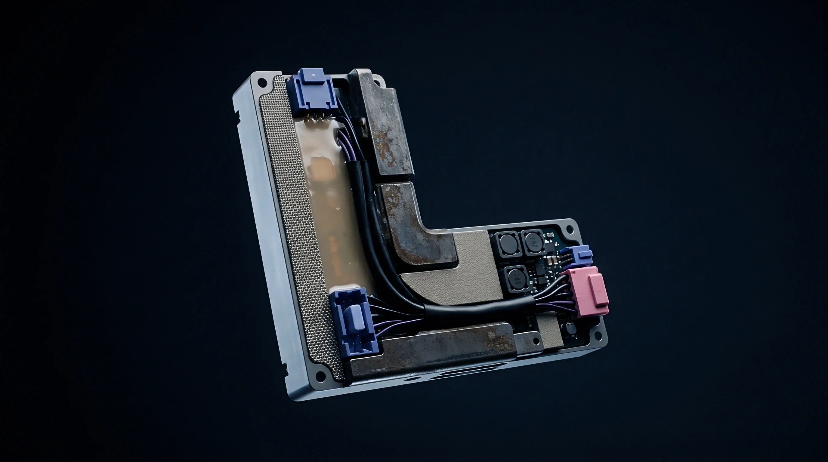
Specifying radio hardware requires evaluating total radiated power under real-world grip constraints. Procurement teams inspect vendor power handling datasheets to ensure tuning components withstand severe mismatch without accelerated aging, since selecting tuners with low series resistance and high voltage breakdown margin secures longer field operational life. Procurement teams that evaluate radio modules under severe impedance mismatch avoid unexpected field failures while maintaining battery performance specifications.