eUICC Energy Footprint during Initial Network Registration
Initial eUICC registration draws sustained peak current during crypto handshakes and band scans, demanding capacitive buffering and limited band search masks.


Pulse
Powering up an embedded Universal Integrated Circuit Card creates sharp electrical transients well before any RF transmission begins. Once the cellular module receives power, the baseband processor releases the UICC interface reset line to start the electrical handshake across the ISO/IEC 7816-3 serial bus. The Secure Element operating system then runs its cold-boot sequence ~ setting internal memory pointers, checking integrity, and mounting file system tables.
This boot pull sits between 12 mA and 28 mA at 1.8V or 3.0V, holding for 15 to 45 milliseconds before the card returns an Answer To Reset frame.
Current demands spike once the core begins handling cryptographic credentials. Modern eUICC chips rely on dedicated hardware accelerators for asymmetric cryptography, particularly elliptic curve scalar multiplication and RSA signature verification. Running these initial authentication calculations pulls power on par with an active low-power microcontroller, reaching peaks of 35 mA right on the smartcard silicon.
Any supply ripple or momentary dip at the VCC pin during this window risks corrupting internal RAM execution, triggering a UICC reset before the network attach ever shows up on a protocol analyzer.
Power supply droop exceeding 100 mV during ISO/IEC 7816-3 Answer To Reset execution forces the Secure Element into an immediate hardware reset state.
Total device startup draw is easy to underestimate if baseband modem current is measured without accounting for the card slot. Because of operating system complexity and active file system structures, embedded profiles draw considerably more energy at boot than legacy SIM cards. Power rails have to remain steady while both the baseband and smartcard run their self-tests at the same time.

Smartcard Core Energization and ISO Interface Handshake
Electrical startup must adhere to strict timing windows set by ISO standards and GSMA requirements. Voltage rails on the contact pads need to ramp smoothly, without ringing or overshoot. Once the clock stabilizes, the baseband toggles reset high and expects an ATR byte sequence within 400 to 40,000 clock cycles.
Current rises predictably as the clock starts, though brief spikes appear when internal charge pumps activate non-volatile memory rails inside the Secure Element.
Clock frequencies change during protocol negotiation. Signaling starts at the default 3.57 MHz base clock, but ISO/IEC 7816-3 parameter selection can shift the bus up to 10 MHz or beyond. That higher frequency shortens transaction time, but it raises dynamic CMOS switching current on the VCC rail.
Power budgets must account for this sudden thermal and current jump, especially when operating from low-capacity primary batteries prone to brownouts.

Cryptographic Engine Peak Loads during Bootstrapping
Authenticating the profile requires substantial math on the card itself. At first attach, the baseband passes an authentication challenge to the USIM application on the eUICC, which runs Milenage or TUAK against 128-bit or 256-bit secret keys using random challenge values sent from the tower.
These co-processor calculations generate distinctive, sharp current steps visible on high-bandwidth probes. Hardware acceleration engines fire in rapid bursts, creating steep current transients that place heavy demands on local decoupling capacitors. If the PCB lacks adequate local ceramic storage, the resulting rail noise degrades receiver sensitivity right as the radio begins scanning for cells.
- Secure Element brownout during ATR transmission, forcing continuous hardware reboot cycles before baseband initialization.
- Clock frequency misconfiguration driving interface current above rated battery continuous discharge capabilities.
- Unfiltered charge pump noise coupling directly into sensitive low-noise amplifier supply rails on the RF front end.
- Excessive internal resistance causing high supply rail voltage drop during simultaneous modem boot and card crypto execution.
Datasheets frequently quote low average standby power figures while omitting the duration of peak current spikes during cryptographic execution.


Handshake
Remote SIM provisioning depends on layered security sessions spanning the cellular access stratum and transport security layers. Under GSMA SGP.22 and SGP.32, the eUICC must establish credentials, pull down profile metadata, and write full operator profiles over the air. The energy spent doing this dwarfs standard network registration, turning a routine attach into an extended, compute-heavy session.
The TLS connection between the module’s Local Profile Assistant and the Subscription Management Data Preparation Plus platform requires mutual authentication. Both sides exchange public key certificates, verify trust chains back to stored roots, and derive session keys via Elliptic Curve Diffie-Hellman. Depending on profile structure, elementary file counts, and carrier applets, initial download payloads run anywhere from 20 kilobytes to 120 kilobytes.
| Protocol Execution Phase | Duration (s) | Average Current (mA) | Peak Current (mA) | Energy Cost (mAh) |
|---|---|---|---|---|
| Baseband Power-On & UICC ATR | 0.085 | 22.4 | 38.0 | 0.00053 |
| Initial PLMN Scan & RACH Attach | 14.200 | 68.5 | 310.0 | 0.27020 |
| TLS 1.2/1.3 Session Setup & Cert Validation | 2.850 | 112.0 | 145.0 | 0.08867 |
| Profile Payload Download (45 KB) | 8.600 | 95.2 | 280.0 | 0.22742 |
| NVM Desegmentation & Flash Write | 1.450 | 32.0 | 48.0 | 0.01289 |
| Final RRC Release & PSM Transition | 0.320 | 18.5 | 22.0 | 0.00164 |
| Test Conditions: LTE-M Cat-M1, Transmit Power +10 dBm, RSRP -98 dBm, 3.6V Lithium Thionyl Chloride battery supply. | ||||
Storing the incoming profile means writing directly to flash or EEPROM inside the Secure Element. Erasing and writing flash pages requires stable internal voltages from card charge pumps; writing a 60 KB profile structure draws 15 mA to 25 mA continuously on the card rail for over 1000 milliseconds, independent of what the RF receiver is pulling.

Over the Air Profile Download Protocol Overhead
Low-power wide-area links carry substantial protocol overhead. Delivering a profile over LTE-M or NB-IoT accumulates headers across IP, UDP/TCP, TLS, and APDU layers. Once expanded by certificate chains, even modest payloads keep modems out of sleep, pinning them in active Radio Resource Control connected mode for seconds at a stretch.
Poor Signal-to-Interference-plus-Noise Ratios compound this energy cost through retransmissions. Weak coverage drives up block error rates, triggering HARQ retries and pushing transmit power toward maximum limits (+23 dBm or +20 dBm). At those levels, uplink bursts pull up to 450 mA.
When sustained crypto operations overlap with full-power RF transmission, battery reserves take a heavy hit during initial deployment.
GSMA SGP.22 Section 5.3 mandates TLS session termination and full profile package rejection if cryptographic validation fails during payload transfer.

Secure Element NVM Allocation and Cryptographic Verification
Incoming profile containers arrive as encrypted, BER-TLV encoded structures that the eUICC must decrypt and validate against vendor signatures in real time. The Secure Element processor parses and checks these signatures line by line as blocks load into RAM.
Writing to non-volatile memory carries a fixed energy cost per byte. Clearing sectors ahead of applet installation relies on internal high-voltage pulses that draw directly from the primary supply. If decoupling is insufficient during flash programming, incomplete writes can corrupt the profile, requiring manual recovery or card replacement.
Carrier agreements routinely define strict session timeouts for activation, penalizing devices that keep channels tied up during sluggish profile transfers.


Scan
A fresh eUICC device straight from assembly powers up without an acquisition database, channel history, or saved network parameters. The modem must run a full raster search across every supported frequency band to find an available Public Land Mobile Network, burning through significant charge before achieving synchronization.
The receiver stays active throughout the scan. Low-noise amplifiers, local oscillators, and ADCs run at full performance to catch weak signals across broad bands. Searching a single LTE band across standard rasters draws 45 mA to 85 mA at 3.8V and takes anywhere from 2 to 15 seconds, depending on channel conditions and bandwidth configuration.
Out-of-the-box modem firmware often defaults to searching dozens of global bands. Cycling through 20 separate 3GPP bands will drain small battery reserves before the device ever registers on a cell, leaving unchargeable field hardware critically depleted.
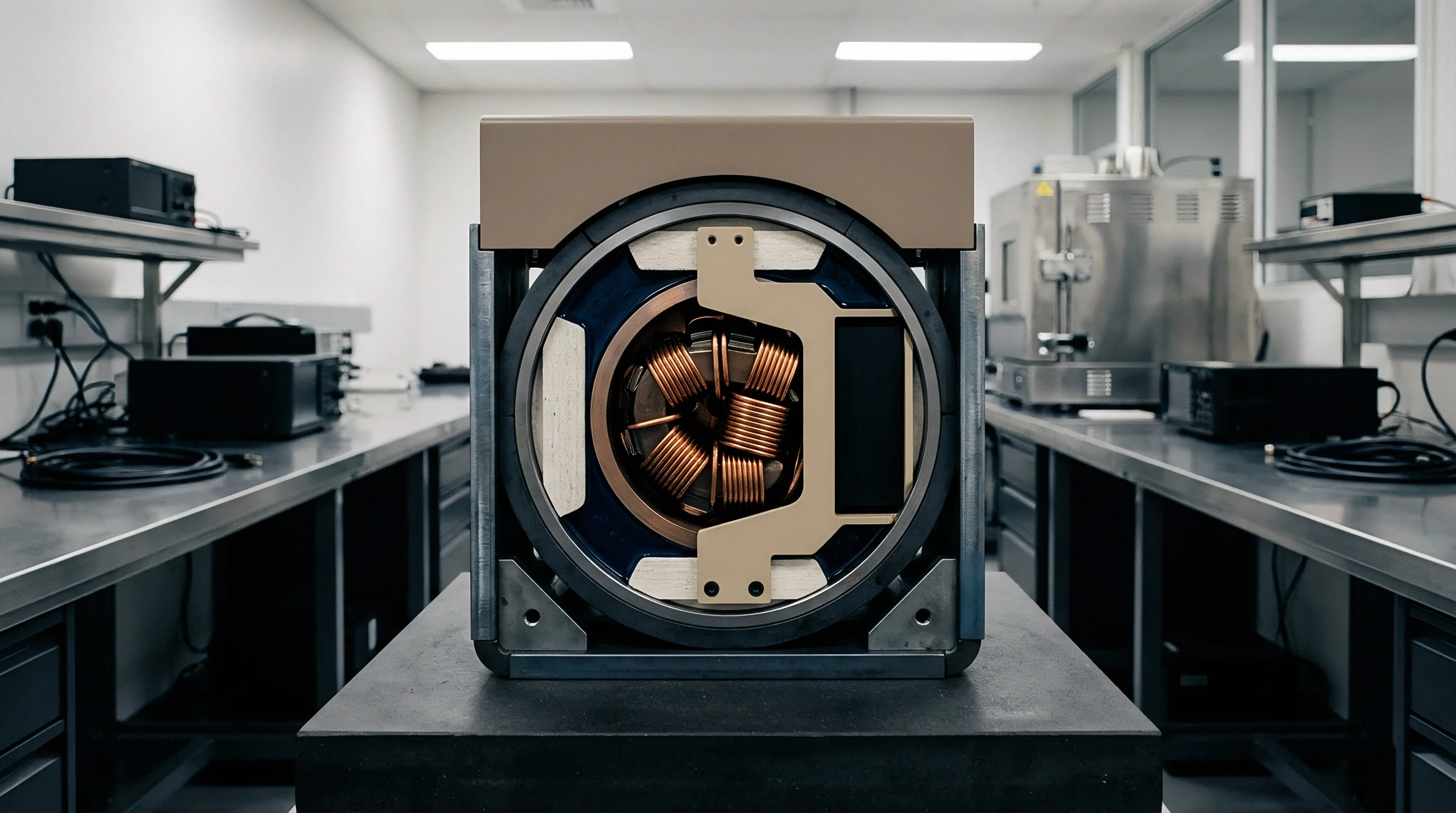
Which Band Raster Configurations Avoid Excessive Initial Attach Battery Depletion?
Restricting the acquisition search space is the most direct way to limit attach energy. Pre-loading firmware with regional band masks cuts scanning time from minutes to seconds by skipping unused allocations. Confining the scan to target bands minimizes modem run time and preserves cell capacity for actual registration traffic.
Raster step sizes present a direct trade-off between coverage and battery life. Fine-raster steps detect marginal carriers at the cost of prolonged scan times. Coarser steps find strong local cells quickly and reduce receiver energy use, though they may miss cells near coverage boundaries.
- Modem bootloader loads factory configuration files containing restricted deployment band masks.
- RF front end initializes low-noise amplifier gain tables tuned specifically for target regional carrier frequencies.
- Baseband receiver executes fast Primary Synchronization Signal scans across primary channel rasters.
- Modem decodes System Information Block Type 1 messages to assess network access suitability and PLMN compatibility.
- Random Access Channel preamble sequence transmits at minimum estimated power based on received signal path loss.
- RRC Connection Request completes, transitioning modem state from idle search to active network session.

Baseband Receiver Power States during PLMN Selection
Candidate cell evaluation requires decoding cell-specific reference signals from broadcast System Information Blocks. Parsing SIB1 and SIB2 keeps baseband processors and RF paths fully powered for hundreds of milliseconds on every viable candidate.
Dense RF environments with multiple overlapping carriers increase processing overhead. The baseband has to evaluate Reference Signal Received Power and Quality across competing cells, cross-referencing priority rules against roaming lists on the eUICC. The resulting APDU back-and-forth between modem and Secure Element holds the chip out of low-power sleep.
Leaving global scanning enabled on battery-powered trackers can exhaust a primary cell within days of warehouse provisioning.


Charge
Cellular modules draw distinct, compounding current spikes during first-time identity verification. Total charge consumed is the integral of this current across the full duration of the connection. While eDRX and PSM drop idle draw down to microamps later on, the initial boot and profile attachment cycle requires sustained milliamp-level current.
Battery chemistry often dictates whether a device survives this initial attach. Primary Lithium Thionyl Chloride cells offer high energy density but form an internal passivation layer during storage. When hit with simultaneous current draws from the eUICC crypto engine and the RF power amplifier, passivated cells exhibit sharp voltage drops that can cross below module undervoltage lockout limits.
| Battery Chemistry Type | Nominal Voltage (V) | Max Continuous Current (mA) | Pulse Current Capability (mA) | Passivation Risk Level |
|---|---|---|---|---|
| Lithium Thionyl Chloride (LiSOCl2) Bobbin | 3.6 | 25 – 50 | 80 – 130 | Severe |
| LiSOCl2 + Hybrid Layer Capacitor (HLC) | 3.6 | 150 – 250 | 1000 – 2000 | Low |
| Lithium Manganese Dioxide (LiMnO2) | 3.0 | 100 – 200 | 400 – 1000 | Negligible |
| Lithium Iron Phosphate (LiFePO4) Rechargeable | 3.2 | 500 – 1000 | 3000 – 5000 | None |
Paralleling a hybrid layer capacitor or supercapacitor buffers the cell against peak transmit and cryptographic spikes. The capacitor supplies immediate pulse current, while the primary battery recovers during lower-drain periods. Sizing these networks requires budgeting for eUICC provisioning, where the sustained baseline draw is noticeably higher than during a standard network ping.

Primary Battery Passivation and Instantaneous Voltage Dips
Storage causes a thin lithium chloride film to grow on the lithium anode. This passivation layer raises internal cell resistance, choking off sudden current delivery. When the eUICC kicks off cryptographic verification or the modem pulses the power amplifier, output voltage drops sharply.
Firmware-driven depassivation must run before attempting remote provisioning. By pulsing a dummy load, the software burns off the passivation layer and restores lower internal resistance. Skipping this step leads to boot loops: the device powers up, attempts authentication, sags below the brownout threshold, resets, and repeats the cycle until the battery is flat.
Incorporating parallel hybrid layer capacitors converts sharp 500 mA load steps into smooth 30 mA battery discharge profiles.

Capacitive Buffering and Active Rail Regulation
LDOs feeding the smartcard require carefully chosen output capacitance to stay stable during fast load steps. Switching transients within the Secure Element core introduce high-frequency noise onto the supply lines. Placing ceramic capacitors within millimeters of the UICC contacts shunts this noise and keeps rail voltage steady.
System PMICs also need fast transient response. Buck-boost stages should transition smoothly between light-load idle states and high-load transmit pulses. Sluggish regulation causes transient rail sags that trip modem brownout protection during active profile writes.
- Select battery chemistry capable of delivering required continuous current without experiencing destructive passivation drops.
- Implement controlled depassivation sequences in software before enabling high-power cellular baseband operations.
- Place local ceramic capacitance within close proximity of the eUICC supply pins to dampen localized switching transients.
- Configure conservative brownout thresholds in modem firmware to prevent repeated unexpected processor resets.
A reliable sizing rule is to design the power source’s pulse capacity to handle twice the combined peak current of RF transmission and smartcard flash writes.


Directive
Hardware purchase orders and modem configuration files must set hard limits on provisioning energy. Engineering specifications should explicitly cap peak current and total energy usage during the initial deployment sequence. Leaving peak current, download energy budgets, and band limits out of supply contracts leaves deployments vulnerable to field brownouts and disputed battery claims.
Carrier certification tests verify RF compliance and network compatibility, not startup power efficiency. Integrators must develop test procedures that track total microamp-hours from first power-up through to PSM entry. These validation suites need to record current profiles under weak coverage, using high-resolution test gear.
- Mandatory band selection masks pre-loaded into module non-volatile memory prior to device assembly.
- Maximum allowable energy threshold allocated for remote SIM provisioning profile downloads under bad coverage conditions.
- Defined network attach timeout limits that force baseband sleep transitions when acquisition attempts fail.
- Guaranteed maximum peak current ratings for smartcard VCC rails under all active operational modes.
Modem configurations require explicit backoff logic. If network attach fails because of weak signal, missing cells, or server-side auth errors, software timers must drop the baseband into sleep. Exponential or linear backoffs prevent continuous scanning from turning a transient network drop into a permanent battery failure.

Sourcing Specifications for eUICC Provisioning Budgets
Manufacturer datasheets generally reflect ideal laboratory conditions. Procurement contracts need specific addendums covering real-world attach figures. Sourcing terms must bind suppliers to maximum current limits under worst-case link conditions, including highest transmit power and maximum coding overhead.
Clear performance benchmarks make power efficiency enforceable across suppliers. Contracts should state maximum microamp-hour limits for cold boots and remote profile installations, making successful bench verification a formal prerequisite for production sign-off.

Fallback Timers and Network Retry Thresholds
Recovery routines are essential software safeguards. If an eUICC fails to validate or an RSP server stops responding, the modem must abort after a fixed window. Without strict caps, endless scan-and-retry loops will drain a primary battery in a matter of hours.
Exponential backoff algorithms ensure failed connection attempts consume exponentially decreasing energy over time.
Choosing attach timeouts requires balancing connection reliability against battery life. Short windows save power but can strand devices in fringe coverage; long windows improve connect rates in weak RF environments at the expense of running the battery down when no network is reachable.
How much energy should a cellular module be permitted to spend on initial eUICC profile provisioning before aborting the session completely and locking into a low-power recovery state?