Determining Antenna Equivalence for Host Modular Approvals
Antenna equivalence requires matching passive peak gain and directivity profile within certified limits to maintain host modular approval without re-filing.


Gain
Regulatory compliance for transmitter integration relies on maintaining strict boundaries around radiated output power. When a host system incorporates an approved transmitter module, Federal Communications Commission regulations under 47 CFR Section 15.204 and Innovation, Science and Economic Development Canada provisions in RSS-GEN Section 6.8 permit antenna substitution only when the proposed candidate demonstrates equivalency. The primary metric governing equivalence is passive gain, which represents the isotropic ratio of radiated power density in the direction of maximum beam intensity compared to an ideal point source.
Substituting an antenna with higher peak gain increases the effective isotropic radiated power beyond the level evaluated during original module certification, altering the fundamental emissions baseline.
The grant certificate issued by a Telecommunication Certification Body specifies the exact maximum gain approved for each operating frequency band. An integrator seeking to substitute a component must evaluate gain specifications across the entire operational frequency range rather than comparing single midpoint figures. A substitute component showing lower gain at 2400 MHz might exceed certified peak gain at 2483.5 MHz due to internal physical resonance shifts.
Exceeding certified peak gain in any active channel invalidates the original authorization, rendering the host system non-compliant without further regulatory filings.
Equivalent gain requirements enforce identical or lower passive amplification across all elevation and azimuth planes. Integrators frequently confuse conductive power delivered to the antenna terminal with effective radiated power emitted into free space. Because passive gain directly scales radiated field strength, a 3 dB increase doubles the radiated power density in the main lobe direction.
This scaling affects both intentional radiation inside the operating band and harmonic emissions in restricted bands designated under 47 CFR Section 15.205.

Peak Gain Limits across Operating Frequency Bands
Certifying modular radio hardware establishes an upper boundary on passive amplification across specified transmission channels. Testing houses document peak isotropic gain measured in dBi or peak gain relative to a half-wave dipole in dBd. Converting between these units requires adding 2.15 dB to dipole gain figures to derive isotropic equivalent values.
A candidate component rated at 1.5 dBd offers 3.65 dBi isotropic peak gain, which exceeds a grant limited to 3.0 dBi. Antenna manufacturers frequently publish typical gain figures on commercial datasheets, but regulatory evaluations demand worst-case maximum gain figures across production tolerance bands.
Manufacturing tolerances in ceramic chip antennas or printed circuit board trace elements introduce gain variations of 0.5 dB to 1.5 dB across production lots. Integrators must verify that upper production limits remain at or below the certified grant maximum. When evaluating multi-band modules operating across 2.4 GHz, 5 GHz, and 6 GHz Wi-Fi spectrum, gain equivalence must hold for every individual band.
A candidate antenna satisfying gain constraints in the 2.4 GHz band while breaching the 5.8 GHz grant limit fails total equivalence criteria.
Peak passive amplification limits listed on a grant certificate apply independently across every supported frequency band.

Conducted Power Interactions with Antenna Mismatch
Terminal impedance variations at the feed point alter the RF energy delivered from the power amplifier into space. Antenna matching networks compensate for complex impedance shifts between a 50-ohm transmitter output and the load. An input impedance imbalance causes voltage standing wave ratio increases, reflecting a portion of the conducted power back toward the transmitter output stage.
While impedance mismatch decreases transmitted power, inserting an active matching network or changing antenna geometry can alter overall system radiator efficiency.
Radiation efficiency defines the ratio of total radiated power to input power accepted by the antenna feed line. High-efficiency substitute antennas convert a higher percentage of conducted energy into radiated fields. If the original modular grant baseline was established using an antenna with 50 percent total radiation efficiency, substituting an antenna with 85 percent efficiency elevates total radiated power even if peak directional gain numbers match on paper.
Compliance engineers verify total radiated power alongside peak directional gain during substitution reviews.
| Regulatory Authority | Governing Standard | Gain Equivalence Rule | Permissive Change Threshold |
|---|---|---|---|
| FCC (USA) | 47 CFR 15.204 / KDB 996369 | Equal or lower peak gain within same family | Class II Permissive Change required if gain increases |
| ISED (Canada) | RSS-GEN Sec 6.8 / RSP-100 | Equal or lower peak gain within certified type | Class 4 Permissive Change required for higher gain |
| EU (RED) | ETSI EN 300 328 / EN 301 893 | In-band e.i.r.p. limits enforced at host DoC | Re-assessment under RED Article 3.2 required if e.i.r.p. shifts |
| MIC (Japan) | Radio Law Art. 38-24 | Exact antenna specified in type certificate | Construction Type Alteration required for substitute types |
| Data compiled from current published regulatory guidance documents for modular transmitter integrations. | |||
Determining gain equivalence across global jurisdictions requires adjusting evaluation protocols to match regional enforcement frameworks. United States and Canadian regulators lock authorization to maximum peak gain per antenna family. European market entry under the Radio Equipment Directive relies on effective isotropic radiated power compliance of the combined host system, shifting responsibility to host manufacturers during technical construction file updates.
Asian markets such as Japan require listing specific antenna model numbers on the certificate, treating any physical part substitution as a formal modification filing.
Uncertainty in datasheet gain claims introduces risk during market enforcement audits. Component suppliers measure antenna gain on standard laboratory evaluation boards measuring 100 mm by 100 mm. Installing that same antenna inside a small handheld terminal alters ground plane coupling, shifting peak gain magnitude and resonant frequency, so an integrator assuming factory datasheet gain remains unchanged inside a custom enclosure risks regulatory non-compliance.

Pattern
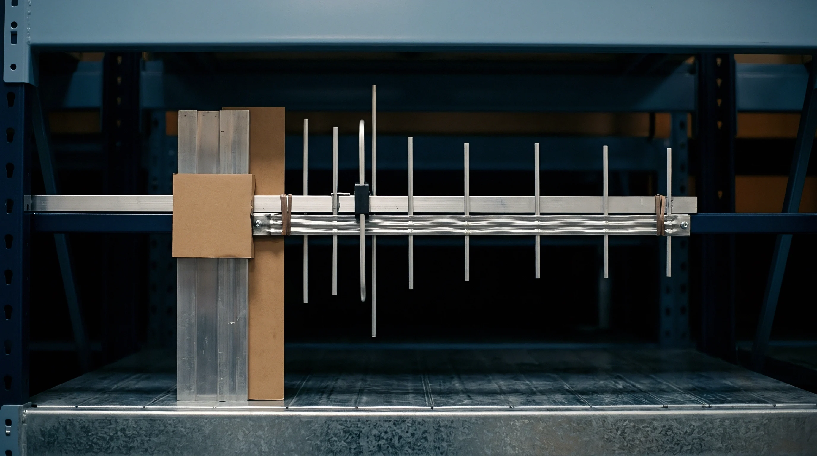
Polar distribution of radiated energy defines how a radio system interacts with surrounding electromagnetic space. Antenna equivalence extends beyond numerical gain figures to encompass physical directional characteristics. Regulators group antennas into structural classifications, including omnidirectional dipoles, planar inverted-F antennas, ceramic patch structures, and directional array elements.
Substituting across structural families invalidates modular approval assumptions even when peak gain metrics remain identical: a directional patch antenna concentrating power into a narrow beam generates localized electric field intensities vastly different from a half-wave dipole emitting energy in a toroidal distribution.
Beamwidth parameters quantify the angular spread of radiated energy between half-power points on a polar radiation plot. Narrowing the main lobe beamwidth concentrates energy, increasing localized power density. Secondary or side lobes project unintended radiation into off-axis angles; during compliance testing, side lobe energy can align with physical host enclosure slots or chassis seams, amplifying radiated spurious emissions.
Host enclosure geometry distorts spatial distribution through near-field scattering and reflection. Placing a substitute element near metallic battery casings, displays, or internal wiring harnesses shifts the phase center of the radiator. These structural interactions degrade omnidirectional properties, forming directional nulls and localized radiation peaks that alter how energy presents to test receiving antennas during chamber scans.

Classifying Antenna Families and Directivity Profiles
Electromagnetic structures categorized under equivalent electrical topologies exhibit similar geometric distribution of radiated power. Regulatory agencies recognize distinct antenna family classifications based on operating mechanisms. Dipoles, monopoles, and whip antennas form the omnidirectional linear radiator family.
Microstrip patch elements, slot radiators, and cavity-backed planar designs constitute directional or semi-directional families, while PCB trace antennas, including meandered inverted-F designs, form a host-dependent family reliant on board ground planes.
Substituting a monopole with a ceramic chip antenna changes the radiator family classification. Monopoles rely on symmetrical RF currents flowing across an underlying ground plane, generating vertical polarization dominance. Chip antennas utilize internal dielectric loading to reduce physical dimensions, generating complex elliptical polarization profiles with significant cross-polarized components.
These structural differences alter near-field coupling factors, preventing direct claims of antenna equivalence without re-testing.
A 2 dBi increase in passive directivity reduces the radiated spurious emission margin by 2 dB in the main lobe direction during 3 meter chamber evaluations.

Radiated Spurious Emissions and Beam Steering Effects
Harmonic energy generated within non-linear transmitter components propagates into three-dimensional spatial coordinates based on physical geometry. Power amplifiers produce harmonic content at integer multiples of the fundamental frequency, such as 4.8 GHz or 7.2 GHz for a 2.4 GHz transmission channel. The physical length of a radiator determines its electrical size relative to harmonic wavelengths; an antenna operating as a compact half-wave radiator at the fundamental frequency behaves as a multi-wavelength array at higher harmonic frequencies, creating sharp high-gain grating lobes.
Beam steering behavior occurs when structural variations in substitute antennas shift high-frequency harmonic lobes into unexpected orientations. While fundamental frequency radiation might comply with omnidirectional targets, third-harmonic energy can form narrow beams with effective peak gains exceeding 6 dBi. If a harmonic beam aligns with a turntable angle during accredited laboratory testing, measured field strength can breach restricted band limits specified in FCC Section 15.209.
- Ground Plane Truncation altering the effective counterpoise length creates unexpected back-lobe radiation and degrades main-lobe gain.
- Metallic Enclosure Proximity Shift detunes the resonant frequency and introduces unpredicted parasitic re-radiation lobes.
- Harmonic Beam Sharpening forms high-intensity directional spikes at secondary and tertiary carrier frequencies.
- Cross Polarization Mismatch transfers energy into alternate polarization vectors, breaching restricted band field strength limits during chamber rotation.
Evaluating radiation pattern equivalence requires three-dimensional spherical power integration. Test engineers capture spatial cut plots across vertical and horizontal polarization planes at 15-degree resolution increments to compare normalized radiation pattern overlays and identify beam pattern distortion. If the envelope of the candidate antenna pattern exceeds the reference antenna pattern at any spatial orientation by more than standard measurement uncertainty margins, equivalence claims fail, requiring host-level permissive change procedures.
Modifying antenna directivity alters system performance within complex host enclosures. Installing a high-directivity candidate inside a metal-framed industrial tablet can reflect radiated energy internally, boosting coupling onto high-speed digital buses. The resulting near-field noise increases systemic spurious floor levels, and ignoring radiation pattern deviations exposes manufacturers to product recall actions and regulatory fines.


Margin
Verification inside anechoic test enclosures quantifies compliance headroom across all active operational modes. Obtaining modular transmitter approval requires testing hardware in a standalone evaluation rig to provide optimal RF ground planes and uninhibited free-space radiation paths. Integrating that module into a commercial product introduces structural metal, shielding cans, power supplies, and logic boards that consume safety margins demonstrated during initial certification.
A module showing 10 dB clearance against spurious emission limits on a reference board may operate with less than 1.5 dB headroom inside a dense host assembly.
Chamber measurement uncertainty accounts for calibrated instrumentation tolerances, antenna factor errors, cable loss variances, and chamber reflection anomalies. Standard CISPR 16-4-2 guidelines establish expanded measurement uncertainty values between 4.0 dB and 6.0 dB for radiated field strength testing above 1 GHz. When compliance margins fall below measured chamber uncertainty thresholds, test laboratories cannot guarantee regulatory compliance across mass production units.
Antenna substitution directly erodes operational clearance when candidate components alter impedance matching or radiation efficiency. High-gain or poorly matched antennas increase harmonic energy generation within the transmitter output filtering stage. When harmonic frequencies approach restricted band thresholds, even sub-decibel increases in radiated output cause test failures, forcing product redesigns late in commercial development cycles.

Chamber Delta Scans and Spurious Emission Baselines
Comparing baseline noise floors between initial evaluation platforms and fully assembled enclosures reveals parasitic coupling. Radiated spurious emission testing requires rotating the host platform 360 degrees on a motorized turntable while raising and lowering the measurement antenna between 1 meter and 4 meters height. This process sweeps a cylindrical volume around the product, capturing maximum field strength vectors across frequency spans from 30 MHz to 40 GHz depending on transmitter carrier frequency.
Pre-scan procedures utilize fast peak-detector spectrum analyzer sweeps to identify potential frequency spikes. Any emission approaching within 6 dB of quasi-peak or average regulatory limits undergoes formal azimuth and height maximization using calibrated average and quasi-peak detectors. Substituting an antenna alters both the frequency location and amplitude of these peak emissions, and an antenna with uncalibrated internal resonances can introduce spurious spikes at non-harmonic frequencies due to parametric oscillations in the front-end matching circuit.
Section 15.204 of 47 CFR voids the host modular authorization if an unapproved antenna type or higher gain model is connected without administrative submission.

Does Antenna Directivity Alter Portable RF Exposure Classification?
Spatial concentration of electromagnetic energy in close proximity to human tissue modifies localized specific absorption rate profiles. Portable host devices operating within 20 centimeters of a user body require evaluation under FCC KDB 447498 D01 and ISED RSS-102 health safety standards. Modular grants frequently establish mobile exposure classifications assuming separation distances exceeding 20 centimeters, so substituting a higher directivity antenna inside a portable host platform alters spatial energy distribution and can exceed localized power density thresholds.
Specific absorption rate measurements quantify energy absorption per unit mass of tissue, expressed in watts per kilogram. Focused radiation beams generated by high-gain or narrow-beam substitute antennas concentrate energy into smaller tissue volumes, raising peak 1-gram or 10-gram average SAR levels. An antenna substitution that maintains total e.i.r.p. compliance can still fail portable SAR exposure limits if directivity sharpens field intensity near the host outer casing.
- Mount the reference host assembly containing the original certified module and antenna onto the turntable inside a fully calibrated semi-anechoic chamber.
- Execute full 3D spatial radiated spurious emission scans across all operational frequency channels, recording peak baseline field strength levels.
- Replace the original antenna element with the proposed candidate component, maintaining identical physical mounting orientation and feed cable routing.
- Repeat 3D spatial radiated emission sweeps, comparing maximized harmonic field strengths directly against baseline measurements.
- Evaluate power density or SAR compliance metrics if the host application falls under portable RF exposure classification rules.
| Test Frequency (MHz) | Regulatory Limit (dBµV/m) | Original Module Baseline (dBµV/m) | Substitute Antenna A (dBµV/m) | Substitute Antenna B (dBµV/m) | Compliance Status |
|---|---|---|---|---|---|
| 2412.0 (Fundamental) | 125.2 (Peak e.i.r.p.) | 98.4 | 98.1 | 101.2 | Compliant (All) |
| 4824.0 (2nd Harmonic) | 54.0 (Average) | 44.2 (Margin 9.8 dB) | 46.8 (Margin 7.2 dB) | 52.8 (Margin 1.2 dB) | Antenna B High Risk |
| 7236.0 (3rd Harmonic) | 54.0 (Average) | 42.1 (Margin 11.9 dB) | 48.5 (Margin 5.5 dB) | 55.1 (Margin -1.1 dB) | Antenna B Non-Compliant |
| 12060.0 (5th Harmonic) | 54.0 (Average) | 39.5 (Margin 14.5 dB) | 41.2 (Margin 12.8 dB) | 43.0 (Margin 11.0 dB) | Compliant (All) |
Data captured in chamber evaluations highlights how harmonic energy scales non-linearly with antenna structural changes. Antenna B exhibits a 2.8 dB gain increase at fundamental frequencies, but secondary structural resonances create a 13.0 dB spike at the 3rd harmonic. This amplification breaches restricted band limits under 47 CFR 15.205, demonstrating why gain matching on paper does not guarantee passing physical chamber scans.
Module suppliers routinely assure integrators that substitute components passing basic VSWR bench checks will pass regulatory compliance scans. These claims obscure host-dependent coupling behavior, leaving host engineers exposed during final product audit testing.

Filing
Administrative submittals to telecommunications certification bodies establish the legal scope of market authorization. When host integrators swap antennas outside the parameters of an existing modular grant, administrative filings maintain legal distribution rights. Under the FCC framework, substituting an antenna of equivalent type with equal or lower gain requires no formal filing update, provided the host manufacturer retains technical test documentation in internal engineering files.
Substituting a higher gain antenna or changing the antenna family requires filing a Class II Permissive Change or applying for a new equipment authorization.
Permissive change processes vary depending on ownership of the original modular grant. Module grantees execute standard Class II Permissive Changes by submitting candidate antenna specification sheets, 3D radiation plots, and radiated spurious emission test reports generated by an accredited laboratory. If the original module grantee refuses to file a permissive change, the host manufacturer can execute a Change in FCC ID under Section 2.933, followed immediately by a Class II Permissive Change submittal under their own corporate identity.
Canadian RSP-100 regulations mirror FCC mechanisms through Class 4 Permissive Change submittals. European Union compliance under RED rules requires updating the host manufacturer Technical Construction File, after which the host manufacturer signs a renewed Declaration of Conformity asserting compliance with ETSI EN 300 328 standards while assuming legal product liability.
Permissive Change Pathways for Antenna Modifications
Regulatory agencies establish defined categories when modifying certified radio equipment parameters. A Class I Permissive Change covers minor circuit adjustments that do not degrade RF characteristics or increase radiated emissions, requiring no formal agency notification. Antenna substitutions rarely qualify under Class I unless the substitute component is physically identical with lower gain across all frequencies.
Class II Permissive Changes address modifications that alter degraded emission profiles while remaining within baseline statutory limits. Adding a higher-gain antenna or introducing a new structural antenna family triggers Class II procedures, requiring radiated spurious emission test data to demonstrate that harmonic output remains within legal thresholds. In cases where portable exposure conditions apply, SAR evaluation reports must accompany the filing package.
Matching the electrical impedance and radiation classification of an approved reference antenna prevents host re-certification delays.

Trace Layout Guidelines for Integrated Host Antennas
Printed circuit board routing between the module pinout and the radiated element forms an integral part of the certified RF circuit. Under FCC KDB 996369 D02 guidance, modular grants covering microstrip trace antennas lock PCB layout parameters to exact physical specifications. The host integrator must replicate board layer stackup thickness, copper weight, trace width, coplanar ground gaps, and dielectric constant metrics specified in the module manufacturer integration manual.
Deviating from reference trace routing parameters converts a standard modular integration into a custom transmitter design. Changing dielectric substrate material from high-frequency Rogers laminate to standard FR-4 alters microstrip wave velocity and impedance, producing unwanted trace radiation. Microstrip trace layout deviations force host integrators to execute Class II Permissive Changes or obtain full host-level equipment certification prior to commercial distribution.
- Comparative Gain Plot Dossier documenting peak isotropic gain and 3D radiation patterns across all operating bands.
- S-Parameter Touchstone Files providing return loss and input impedance data measured across candidate feed points.
- Radiated Spurious Test Reports issued by an ISO/IEC 17025 accredited laboratory covering harmonic frequencies up to 40 GHz.
- Host Gerber PCB Artwork demonstrating exact adherence to reference microstrip trace dimensions and stackup layer geometry.
Completing documentation packages requires collecting verified technical data from antenna suppliers, accredited test facilities, and internal CAD departments. Omitting Gerber artwork details or submitting uncalibrated antenna pattern plots leads to immediate TCB rejection notices, freezing distribution channels and preventing market entry.
Per FCC KDB 996369 D04 guidance, host integration documentation must confirm that all radiated spurious emissions generated by the combined host system remain compliant with applicable technical rules.


Schedule
Project timelines depend directly on chamber booking availability and agency review turnaround times. Integrating a pre-approved module with a fully equivalent antenna requires zero administrative waiting time, enabling immediate market entry following standard host-level EMC and safety testing. Introducing a non-equivalent antenna triggers laboratory re-testing and permissive change filings, inserting four to twelve weeks into commercial launch schedules.
Laboratory testing schedules vary seasonally. Accredited test facilities experience heavy chamber booking volume during autumn quarters ahead of consumer electronics holiday shipping deadlines. Unplanned re-testing requirements discovered during final host verification force projects back into laboratory queues, compounding project delays and scaling lead times with regulatory complexity.
Global market access strategies require parallel filing sequences. While FCC Class II Permissive Changes process within two to three weeks once test reports reach a TCB, international filings in markets like China, Japan, or South Korea require longer lead times due to local agent representation rules and mandatory in-country sample testing.
Landed Regulatory Costs for Alternate Antenna Approvals
Financial commitments for obtaining host compliance divide between accredited laboratory fees and administrative agent submittals. Conducting radiated spurious emission delta testing in an accredited semi-anechoic chamber costs between $2,000 and $3,500 per day, and a complete permissive change test campaign covering multi-band Wi-Fi and Bluetooth operations consumes two to three full chamber days.
Administrative fees charged by Telecommunication Certification Bodies add $1,500 to $2,500 per permissive change submittal. Executing equivalent filings across international jurisdictions expands landed costs further: in-country testing in Asian or South American jurisdictions requires submitting physical host units, generating freight, customs clearance, and local laboratory testing fees that frequently exceed $10,000 per market.

Sequencing Multi Market Filings to Protect Launch Windows
Global distribution planning mandates precise chronological execution across regional certification authorities. Launching hardware concurrently across North America, Europe, and Asia demands completing baseline FCC and European RED evaluations before submitting paperwork to secondary market authorities. Regulators in countries such as Taiwan, South Korea, and Brazil accept underlying FCC or ETSI test reports to streamline local approvals, provided report formats match current international standards.
Executing permissive changes out of sequence disrupts global shipping schedules. If a host manufacturer alters an antenna design during mid-production, units shipped to European destinations under host DoC rules may pass customs, while identical units shipped to the United States face border hold actions due to missing C2PC grants. Harmonizing antenna substitution submittals across all target markets prevents inventory impoundment at international port facilities.
| Approval Pathway | Laboratory Chamber Hours | Agency Processing Time | Estimated Landed Cost (USD) | Market Access Impact |
|---|---|---|---|---|
| Equivalent Antenna (Self-Verification) | 4 to 8 Hours (Pre-scan) | 0 Weeks (Internal Dossier) | $1,200 – $2,500 | Immediate commercial release |
| FCC C2PC / ISED C4PC Filing | 16 to 24 Hours (Full Radiated) | 2 to 4 Weeks (TCB Review) | $6,500 – $12,000 | Launch delayed 4-6 weeks |
| Host Change in ID + Permissive Change | 16 to 24 Hours (Full Radiated) | 4 to 6 Weeks (Dual Filing) | $9,500 – $16,000 | Launch delayed 6-8 weeks |
| Full Host Re-Certification | 40+ Hours (Complete Radio Suite) | 6 to 10 Weeks (Full Review) | $18,000 – $35,000 | Launch delayed 10-14 weeks |
Choosing between equivalent antenna selection and full host re-certification requires balancing upfront component selection costs against downstream regulatory filings. Standardizing antenna geometry and performance criteria early in mechanical architecture phases eliminates unnecessary permissive change cycles, keeping capital expenditure focused on core product engineering.