Dielectric Dissipation and Skin Depth Interaction in Micro Coaxial Assemblies
Micro coaxial attenuation shifts from conductor loss to dielectric dissipation above 5 GHz, requiring low-loss fluoropolymers to preserve RF sensitivity.

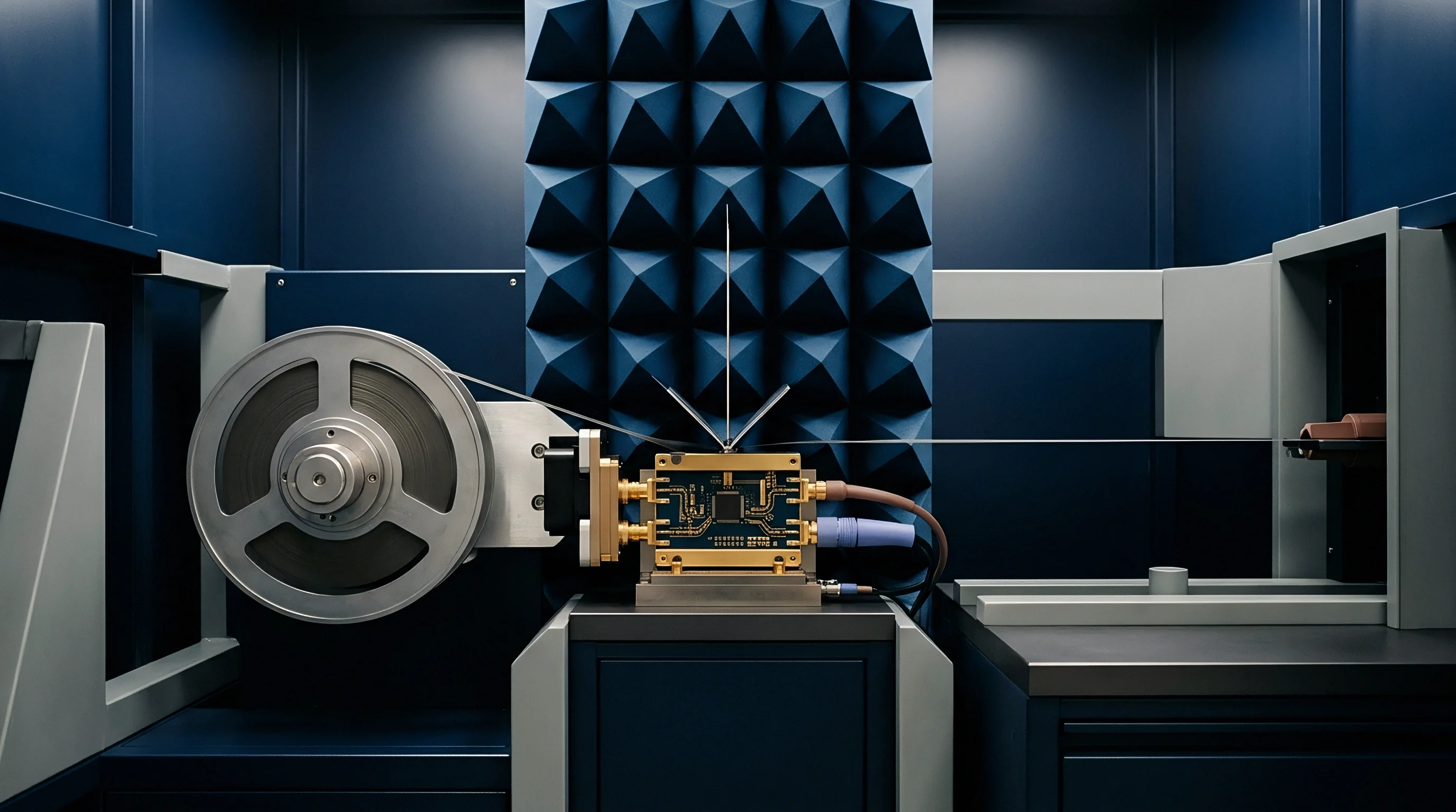
Loss
High-frequency energy traveling through sub-millimeter coaxial structures encounters two distinct physical sinks that scale along different frequency exponents. At lower frequencies, conductor resistance from finite wire conductivity dominates total insertion loss. As operating frequencies move through the 2.4 GHz ISM band into upper 5 GHz, 6 GHz, and 8 GHz allocations, dielectric dissipation increases linearly while skin depth contracts beneath micro-scale surface boundaries.

Skin Depth Boundaries and Conductor Resistance
Conductor skin depth defines the effective depth to which electromagnetic fields penetrate a metal boundary, calculated as the square root of resistivity divided by the product of pi, frequency, and magnetic permeability. At 2.4 GHz, copper skin depth equals 1.34 micrometers. At 6.0 GHz, skin depth contracts to 0.85 micrometers.
Dielectric loss scales linearly. When center wire diameters shrink to AWG 44 (0.05 mm diameter) or AWG 46 (0.04 mm diameter), current crowds into an extremely thin outer ring.
Surface roughness distorts RF current. Micro-scale surface irregularities left by wire drawing dies force high-frequency currents along longer effective path lengths. When root-mean-square surface roughness exceeds the skin depth, conductor loss rises significantly above classical smooth-wall models.
Silver plating thickness matters.

Dielectric Loss Tangent Linear Scaling
Dielectric dissipation accounts for power absorbed directly by the insulating polymer separating center conductor from outer shield braid. Dielectric loss in decibels per meter varies linearly with frequency, proportional to the square root of the relative permittivity multiplied by the dielectric loss tangent. At 1 GHz, dielectric loss in solid Fluorinated Ethylene Propylene remains minor.
At 7.125 GHz, the maximum allocation for Wi-Fi 7, dielectric loss equals or exceeds surface-roughened conductor attenuation.
At 6.5 GHz, a 100 mm silver-plated AWG 44 coaxial cable with solid FEP dielectric exhibits 0.72 dB insertion loss under standard 50-ohm load conditions.
The crossover frequency marks the point where dielectric dissipation surpasses conductor attenuation. Micro coaxial cables featuring high center-wire resistance reach this crossover point between 4.5 GHz and 6.5 GHz. Designing RF jumper traces based on low-frequency attenuation charts leaves high-band radios short of receiver sensitivity targets by over a decibel, truncating coverage footprint before final system sign-off.


Stranding
Internal conductor construction dictates both mechanical durability and high-frequency current distribution inside micro coaxial cables under zero point eight millimeter outer diameter. Portable radios and compact module enclosures require flexible interconnects capable of surviving assembly flexure without cracking.
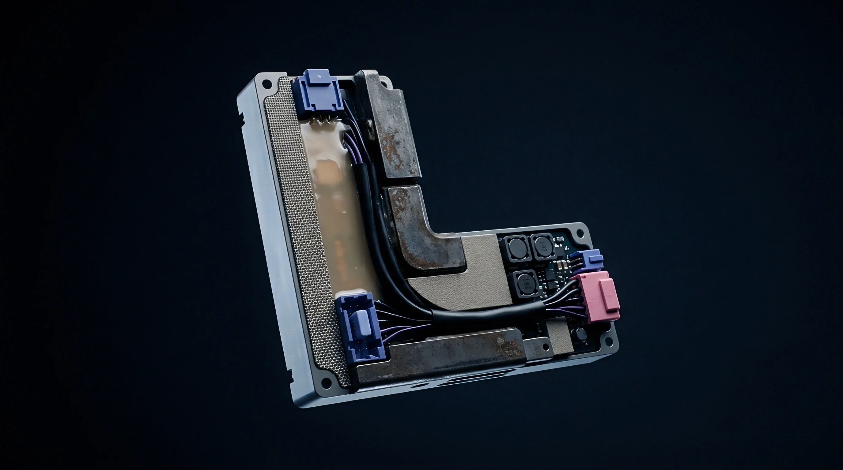
Stranded Wire Proximity Effects
Seven-strand center conductors (7/0.025 mm or 7/0.032 mm) provide flex fatigue resistance compared to solid cores. However, proximity effects between individual strands alter current concentration. Current shifts into silver layers.
Outer strands carry the majority of RF current, while inner contact boundaries introduce micro-voids that disrupt uniform field propagation.

Is Silver Plating Effective above Seven Gigahertz?
Silver plating provides superior conductivity at the outer boundary where skin depth is narrowest. Plating thickness must maintain a uniform depth of at least two skin depths to prevent field penetration into underlying copper alloys. At 8.0 GHz, two skin depths in silver equate to 1.4 micrometers.
If plating thickness drops below one micrometer due to uneven die wear, RF current spills into higher-resistivity base metals.
- Solid PTFE Insulation delivers a low loss tangent of 0.0002 at 10 GHz, maintaining structural stability around micro center wires under soldering heat.
- Fluorinated Ethylene Propylene lowers manufacturing costs for high-volume assemblies, though its loss tangent of 0.0007 doubles dielectric attenuation at 6 GHz relative to PTFE.
- Expanded Porous PTFE introduces micro-air cavities to lower the effective dielectric constant to 1.3, reducing dielectric dissipation while reducing cable outer diameter.
| Cable Size | Center Wire Type | Dielectric Type | Outer Diameter (mm) | Loss at 2.4 GHz (dB/m) | Loss at 6.0 GHz (dB/m) |
|---|---|---|---|---|---|
| AWG 42 | 7/0.032 mm Silver Copper | Solid PTFE | 0.81 | 2.2 | 3.8 |
| AWG 44 | 7/0.025 mm Silver Copper | Solid FEP | 0.64 | 3.1 | 5.6 |
| AWG 44 | 7/0.025 mm Silver Copper | Expanded PTFE | 0.64 | 2.5 | 4.1 |
| AWG 46 | 7/0.020 mm Silver Alloy | Solid FEP | 0.48 | 4.5 | 8.2 |
Cable vendors frequently attribute unexpected insertion loss spikes at upper band limits to test fixture calibration drift rather than non-uniform plating thickness along fine stranded wires.


Deformation
Mechanical bending inside compact device enclosures alters the concentric spacing between center wire and outer shield wire braids. Precision impedance maintenance relies on holding a constant diameter ratio between shield and conductor.

Impedance Shifts under Mechanical Strain
Physical bending compresses soft fluoropolymer dielectrics. For a micro coaxial cable with an outer diameter of 0.81 mm bent around a 2.0 mm radius corner, dielectric compression decreases center-to-shield spacing on the inner turn radius.
Consider an AWG 42 micro coaxial cable with nominal shield inner diameter of 0.45 mm, center wire diameter of 0.15 mm, and solid PTFE dielectric with relative permittivity of 2.0, producing a nominal characteristic impedance of 46.6 ohms. Bending the cable tight against an internal module frame compresses the local dielectric thickness by 12 percent, dropping shield diameter to 0.396 mm in the bend zone. Recalculating local impedance yields 41.2 ohms.
This 5.4 ohm impedance drop creates a localized discontinuity. Bending degrades impedance matching. The resulting voltage standing wave ratio rises from 1.05 to 1.15, generating transmission ripple across 5.8 GHz and 6.5 GHz bands.
Heat accelerates dielectric creep. Continuous high-power transmission heats the inner wire, permanently locking the eccentric core displacement into the plastic insulator.
- Clean test ports and attach precision SMA adapters to vector network analyzer cables calibrated from 100 MHz to 10 GHz.
- Clamp the micro coaxial connector sub-assembly into a rigid bench fixture maintaining nominal straight geometry to measure baseline return loss.
- Apply a controlled 3.0 mm bend radius using a calibrated routing mandrel while recording continuous S21 insertion loss sweeps.
- Subject the routed assembly to fifty thermal shock cycles between minus forty degrees Celsius and plus eighty-five degrees Celsius inside an environmental chamber.
- Re-measure transmission coefficients to confirm insertion loss drift stays within zero point fifteen decibels of baseline values.
Bending a micro coaxial cable tighter than its specified minimum dynamic bend radius accelerates dielectric displacement and creates permanent return loss ripples across upper frequency bands.
Routing micro coaxial assemblies through sharp metal chassis cutouts without protective grommets risks dielectric pinching that permanently degrades radio range across higher operating channels.


Margin
Radio performance calculations in modern ultra-wideband and Wi-Fi 7 designs depend directly on preserving every tenth of a decibel of RF energy between transceiver output pins and antenna feed points. Cable attenuation converts RF power directly into internal heat.

Impact on Wi-Fi 7 and Ultra-Wideband Sensitivity
Wi-Fi 7 4096-QAM modulation requires an end-to-end signal-to-noise ratio above 38 dB at the receiver baseband processor. Higher frequencies exacerbate attenuation. Modulated signals demand phase purity.
An unmodeled 0.8 dB insertion loss in a 150 mm micro coax jumper degrades receiver sensitivity from -55.0 dBm to -54.2 dBm. Receiver sensitivity drops rapidly. This reduction shrinks operational cell radius in enterprise access points.
Battery-powered UWB asset trackers operating on Channel 9 (7.987 GHz) suffer elevated packet error rates when internal jumper cables introduce unaccounted dielectric absorption. Transmitting at higher power levels to overcome jumper loss increases active battery draw. Cable length dictates link degradation.
- EVM Degradation occurs when phase distortion from cable dielectric dissipation corrupts high-order modulation constellations in multi-gigabit wireless links.
- Thermal Noise Elevation increases effective receiver noise figure when passive insertion losses sit directly ahead of low-noise amplifier front ends.
- Transmit Current Escalation forces power amplifiers to draw higher battery current to deliver identical effective isotropic radiated power at the antenna port.
| Radio Standard | Frequency (GHz) | Jumper Length (mm) | Conductor Loss (dB) | Dielectric Loss (dB) | Total Loss (dB) |
|---|---|---|---|---|---|
| BLE / Zigbee | 2.45 | 100 | 0.22 | 0.06 | 0.28 |
| Wi-Fi 6E | 5.85 | 100 | 0.34 | 0.21 | 0.55 |
| Wi-Fi 7 | 7.125 | 100 | 0.38 | 0.32 | 0.70 |
| UWB Ch 9 | 7.987 | 100 | 0.41 | 0.39 | 0.80 |
| UWB Ch 9 | 7.987 | 150 | 0.61 | 0.59 | 1.20 |
Compliance with IEEE 802.11be EVM limits requires total interconnect loss between module RF pin and antenna connector to remain below one decibel at seven gigahertz.
Engineers continue to debate whether future sub-millimeter coaxial structures can achieve lower dielectric dissipation without compromising mechanical pull-off strength at micro connector crimp points.

Procurement
Sourcing micro coaxial cable assemblies for high-density wireless modules demands strict qualification parameters beyond basic mechanical dimensions. Procurement documentation must lock down dielectric material grades alongside conductor plating tolerances.

Datasheet Discrepancies and RFQ Specifications
Supplier datasheets regularly list attenuation at 1.0 GHz or 2.4 GHz while omitting performance figures at 6.0 GHz or 8.0 GHz. Commercial quotes based solely on low-frequency metrics disguise severe dielectric loss escalation in upper bands. Datasheet specifications demand validation.
RFQs must require complete vector network analyzer S-parameter data across the full operational spectrum.
Second sourcing introduces material variance. Substituting solid FEP for expanded PTFE saves assembly cost but doubles dielectric dissipation loss. Precision sweeps reveal batch defects.
Quality assurance protocols must mandate lot sampling sweeps for insertion loss S21 and return loss S11 across operating temperature boundaries.
Unannounced substitution of solid FEP for expanded PTFE in micro coaxial runs doubles cable dissipation loss across six gigahertz wireless channels.
Inserting a mandatory S21 sweep qualification clause from zero point five to eight gigahertz into purchase contracts prevents suppliers from delivering lower-grade dielectric lots that fail Wi-Fi 7 band limits.