Characterization of RF Micro-Coaxial Cable Insertion Loss Degradation
RF micro-coaxial insertion loss escalates through skin-depth resistance, dielectric loss tangent shifts, mechanical flex displacement, and atmospheric oxidation.


Conduction
High-frequency signal transmission across ultra-fine transmission assemblies relies on electromagnetic energy propagation within tight volumetric constraints. Thin dielectric walls, microscopic wire center leads, and high-density braid constructions compress electromagnetic field boundaries into sub-millimeter cross-sections. In micro-coaxial interconnects with outer diameters spanning 0.81 mm down to 0.21 mm, total attenuation increases exponentially as signal frequencies ascend from sub-GHz bands toward 39 GHz millimeter-wave carrier frequencies.
Understanding insertion loss escalation requires isolating attenuation into two distinct loss mechanisms: resistive dissipation within metallic boundaries and polarization losses inside solid dielectric matrices.
At low operational frequencies, total attenuation follows direct DC conductor resistance, dictated by center wire cross-sectional area and alloy conductivity. As carrier frequencies rise, alternating current redistributes toward the outer periphery of conductors. Skin effect restricts current flow to a shallow surface shell, defined by skin depth where magnetic flux inside the metal forces current density to decay exponentially.
High frequency copper wire skin depth decreases rapidly, compressing conductive cross-sections and driving high RF resistance per unit length.
Attenuation scales from 0.85 dB per meter at 900 MHz to 4.60 dB per meter at 6.0 GHz in 1.13 mm micro-coaxial assemblies operating at 20 degrees Celsius.
Metallic surface finish alters high-frequency current distribution along conductor boundaries. Wire drawing processes produce microscopic longitudinal striations and micro-grooves along outer conductor walls and center copper strands. When skin depth approaches or drops below the root-mean-square surface roughness value, current pathways conform to surface contours rather than following a smooth axial vector.
Longer effective conduction pathways elevate physical AC resistance beyond classical smooth-surface skin effect calculations. Silver plating applied over oxygen-free copper inner conductors mitigates surface roughness degradation because silver exhibits higher bulk conductivity than copper, reducing effective surface resistance when plating thickness exceeds three skin depths at the operating frequency.

Conductor Surface Roughness and Skin Depth Losses
Current distribution along microscopic wire surfaces degrades rapidly as carrier wavelengths shrink. Electromagnetic field penetration into metal surfaces falls to a small fraction of a micrometer at microwave frequencies, concentrating active current within the outer skin layer. Surface profile variations act as microscopic impedance irregularities, scattering current paths and increasing resistive heat dissipation.
Modifications to classical skin depth equations incorporate surface profile correction factors, such as the Hammerstad-Bekkadal model or gradient model formulations. When signal frequency reaches 5.8 GHz, skin depth in pure copper drops to approximately 0.86 micrometers. Surface roughness values exceeding 0.2 micrometers RMS generate a measurable rise in effective conductor loss.
Micro-coaxial assemblies utilizing micro-stranded inner leads experience additional current concentration along individual outer strand boundaries, exacerbating proximity effect losses where adjacent strands force current away from internal contact points.
Silver-plating thickness specifications dictate high-frequency loss stability. Insufficient silver electroplating thickness exposes underlying copper-clad steel or copper-alloy base metals to RF current penetration at lower microwave bands, elevating attenuation. Uniform electroplating over micro-fine center wires down to American Wire Gauge 44 requires precise bath chemistry and tension controls during continuous wire drawing, as localized thin spots create non-uniform loss profiles along a single cable run.

Dielectric Dissipation and Permittivity Roll Off
Electric field vectors bridging inner and outer conductors pass through polymeric insulating materials. High-frequency electric fields periodically reorient microscopic dipole molecules within insulating polymers, generating volumetric dielectric heating. Dissipation losses scale linearly with frequency, competing with skin-effect losses at low microwave frequencies and dominating total cable attenuation above 10 GHz.
Fluoropolymer dielectrics dominated by fluorinated ethylene propylene, perfluoroalkoxy alkanes, and microporous expanded polytetrafluoroethylene define modern low-loss micro-coaxial insulation. Solid fluorinated ethylene propylene exhibits a dielectric constant near 2.1 with a dissipation factor around 0.0003 at 1 GHz. Microporous expanded polytetrafluoroethylene introduces microscopic air pockets into the dielectric matrix, lowering effective relative permittivity toward 1.4 and dropping the dissipation factor significantly.
Lower effective permittivity increases phase velocity while permitting larger center conductor diameters for a given 50-ohm characteristic impedance target, reducing conductor loss simultaneously.
Dielectric loss tangent remains non-linear across ultra-wideband frequency ranges. Polymer relaxation phenomena cause subtle dielectric loss increases within specific frequency windows, altering insertion loss slope profiles. Moisture absorption inside micro-porous expanded structures worsens dissipation factors rapidly, converting physical insulation pockets into high-loss polarization nodes when exposed to atmospheric humidity without sealed jacket barriers.

Micro-Coaxial Construction Geometry and Outer Braid Shielding
Physical spatial dimensions control characteristic impedance, cut-off frequency, and baseline attenuation limits. Maintaining a constant 50-ohm characteristic impedance across micro-miniature cable geometries forces tight ratio control between dielectric outer diameter and center conductor diameter. Smaller cable outer diameters demand finer inner wires, escalating AC resistance per meter.
| Cable Outer Diameter (mm) | Inner Conductor Structure | Dielectric Insulation Material | Attenuation at 2.4 GHz (dB/m) | Attenuation at 5.8 GHz (dB/m) | Attenuation at 18.0 GHz (dB/m) |
|---|---|---|---|---|---|
| 0.81 | AWG 36 Solid Silver Copper | Solid FEP Fluoropolymer | 2.80 | 4.55 | 8.90 |
| 1.13 | AWG 32 Stranded Silver Copper | Solid FEP Fluoropolymer | 1.60 | 2.60 | 5.10 |
| 1.32 | AWG 30 Solid Silver Copper | Solid PFA Fluoropolymer | 1.35 | 2.15 | 4.30 |
| 1.37 | AWG 30 Stranded Silver Copper | Solid FEP Fluoropolymer | 1.25 | 2.05 | 4.10 |
| 1.80 | AWG 28 Solid Silver Copper | Microporous ePTFE Membrane | 0.75 | 1.20 | 2.45 |
Outer shield braid construction balances mechanical flexibility against electromagnetic field containment. Fine micro-braid shields woven from tin-plated or silver-plated copper wire strands cover the dielectric core with optical coverage factors ranging between 85 and 95 percent. Microscopic gaps between intersecting braid strands permit aperture leakage at high frequencies, increasing radiation loss and reducing shielding effectiveness.
Double-braid constructions or conductive foil underlays combined with micro-braids eliminate optical gaps, holding RF radiation within the dielectric core and stabilizing insertion loss performance across gigahertz frequency bands.
Assuming micro-coaxial loss profiles follow a pure square-root frequency dependence across all application bands ignores dielectric dissipation linearity and surface roughness amplification factors, underestimating link losses above 5 GHz.

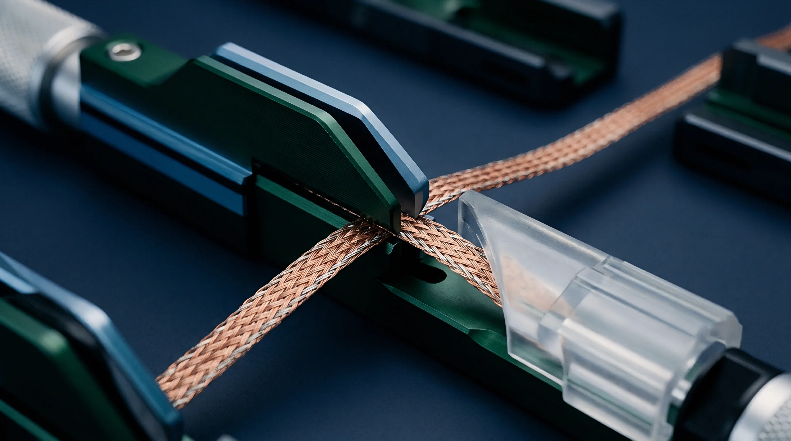
Bend
Deploying micro-coaxial cables inside compact electronic enclosures forces tight routing pathways around internal structural elements, battery wells, and metallic shielding cans. Physical deformation alters cross-sectional symmetry, disrupting the concentric alignment of center conductor, dielectric core, and outer shield braid. When coaxial concentricity shifts, local characteristic impedance deviates from nominal design values, creating reflections and local attenuation spikes.
Flexural forces subject thin metallic components to mechanical strain, driving elastic and plastic material deformation along inner and outer bend radii.
Dynamic flexure applications, such as rotating hinge mechanisms in foldable devices or robotic gimbal assemblies, subject micro-coaxial interconnects to repeated bending cycles. Bending compresses dielectric material along the inner arc while stretching the outer dielectric boundary and outer shield strands. repeated stress cycles induce strain hardening in fine copper wires, altering structural resistance and generating localized physical necking. Physical deformation increases center conductor resistance while altering local capacitance per unit length, degrading total insertion loss over operational lifespans.
Micro-coaxial cable durability depends on the structural integrity of its braided shield layer during mechanical movement. Braid strands slide past one another at crossover points during bending. High friction between overlapping strands leads to strand lock, preventing smooth structural alignment and concentrating flexural stress into localized pinch points.
Strand lock causes braid gaps to widen, increasing aperture size and permitting RF energy radiation away from the central propagation core.
When Does Repeated Mechanical Flexure Drive Irreversible Loss Escalation?
Flex fatigue accumulation begins during initial installation routing and accelerates through dynamic motion cycles. Ultra-fine micro-coaxial cables undergo localized strain during tight-radius bending. Bending radius specifications dictate minimum physical limits below which permanent internal geometry changes occur.
Exceeding minimum bend radius limits compresses the insulating dielectric layer permanently, shifting the inner wire toward the outer shield braid. A reduction in dielectric wall thickness increases localized capacitance and drops local impedance, generating an impedance mismatch point. Reflected RF energy combines destructively with forward-propagating signals, increasing effective insertion loss through standing wave interference rather than thermal dissipation alone.
Dynamic flex testing reveals that insertion loss increases gradually during initial flex cycles, followed by sudden step-function attenuation spikes when individual outer braid strands snap under tension fatigue.
Multi-axis torsional twisting compounds flexural fatigue damage. Twisting forces shift braid lay angles, creating loose structural sections alternating with tightly constricted zones along the cable length. Shield coverage drops in expanded zones, elevating radiation losses while altering phase stability across broadband signal paths.
Inner Conductor Displacement and Impedance Mismatch Discontinuities
Centering precision of inner conductors defines characteristic impedance uniformity along transmission paths. Micro-coaxial cables under structural bending experience radial forces that drive the inner wire through soft polymer dielectrics toward the outer braid. Solid fluoropolymer dielectrics offer higher crush resistance than soft microporous structures, limiting wire movement under static mechanical loads.
Distance shifts between inner conductors and outer shielding layers disrupt capacitance balance per meter. Local impedance drops below 50 ohms at bend locations, forming localized capacitive discontinuities. High frequency signals encounter reflection coefficients at these sites, returning a portion of RF energy back toward the transmitter source.
Cumulative reflections along multiple bend sites create severe return loss degradation (S11) and introduce periodic ripple patterns across insertion loss (S21) spectrum traces.
Single solid inner conductors resist radial displacement better than fine stranded configurations under equal static bend radii. However, stranded wire centers tolerate repetitive flex cycles without physical fracture, whereas solid wires work-harden rapidly and snap under tight dynamic flexure. System designers balance static impedance stability against dynamic flex fatigue resistance when specifying core wire construction.

Outer Braid Shield Strand Fatigue and Aperture Leakage
Braided shield integrity protects signal paths from radiation loss and ambient electromagnetic interference. Micro-coaxial braids utilize ultra-fine wire strands with diameters down to 0.02 mm woven in diamond pattern matrices. Flexural movement drives relative displacement among intersecting braid strands, causing mechanical friction and surface plating wear.
Plating breakdown exposes base copper to atmospheric oxidation and increases contact resistance between intersecting braid wires. Higher contact resistance impedes longitudinal shield current flow, forcing RF current to follow individual helical wire paths rather than a continuous tubular shell. Helical current paths increase outer conductor inductance, elevating shield transfer impedance and degrading attenuation performance across high frequencies.
Severe flexural stress causes strand displacement, expanding rhomboidal apertures between woven braid carriers. Electromagnetic fields leak through expanded openings when aperture dimensions approach fractional signal wavelengths. Radiation leakage converts internal RF energy into ambient electromagnetic radiation, increasing total insertion loss beyond intrinsic material dissipation models.
Neglecting structural strain relief and minimum dynamic bend radius guidelines during micro-coaxial cable installation leads directly to premature cable failure, severe signal reflection, unpredictable attenuation drift, and catastrophic RF link failure in high-vibration operational environments.

Thermal
Environmental thermal swings drive structural dimension shifts and alter electrical transport properties inside RF interconnects. Temperature variations alter electrical resistivity inside metallic conductors and modify complex permittivity inside insulating dielectric polymers. Uncontrolled thermal environments cause attenuation shifts that degrade system link margins during extreme field operations.
Conductor resistivity scales positively with temperature through lattice vibration scattering mechanisms. Rising operational temperatures increase acoustic phonon density within metallic crystal lattices, interfering with electron drift velocity under applied electric fields. Oxygen-free copper inner wires experience a positive temperature coefficient of resistance near 0.00393 per degree Celsius.
Operating a micro-coaxial cable assembly at 85 degrees Celsius increases inner conductor DC resistance by approximately 25.5 percent compared to room-temperature baselines, directly elevating conductor attenuation losses across all frequency bands.
Polymeric dielectric materials exhibit temperature-dependent complex permittivity variations. Thermal expansion changes dielectric density, lowering relative permittivity slightly while temperature shifts modify molecular dipole relaxation rates, altering the dielectric dissipation factor. Thermal expansion coefficient mismatches between inner conductors, fluoropolymer insulation, and outer shield braids generate internal mechanical stress during rapid thermal cycling.

Conductor Resistivity and Temperature Coefficient Dynamics
Metallic conductor loss mechanisms scale directly with absolute operating temperature across automotive, industrial, and defense environments. Surface resistance increases proportionally to the square root of metallic resistivity at high frequencies, dampening RF current amplitudes.
Increases in operating temperature elevate physical skin depth slightly due to higher bulk resistivity. However, elevated resistivity dominates thermal behavior, raising high-frequency surface resistance according to standard electromagnetic relations. At 5.8 GHz, copper surface resistance increases by approximately 12 percent when thermal conditions climb from 20 degrees Celsius to 85 degrees Celsius.
Thin silver plating over copper wires experiences similar thermal loss escalation, raising total insertion loss in long micro-coaxial interconnect runs.
Power handling in micro-coaxial cables introduces self-heating effects that compound ambient thermal stress. High RF power levels passing through fine center conductors generate localized I2R heat dissipation. Thermal dissipation within microscopic volumes raises internal core temperatures significantly above ambient air environments, initiating localized thermal runaway loops where rising resistance increases thermal dissipation further.

Dielectric Expansion and Phase Velocity Shift
Polymer dielectrics swell when exposed to elevated thermal conditions, driving mechanical dimensional shifts inside coaxial assemblies. Volumetric expansion alters internal conductor spacing ratios while modifying dielectric density.
| Dielectric Material Type | Coefficient of Thermal Expansion (ppm/°C) | Dielectric Constant (εr at 20°C) | Dissipation Factor (tanδ at 2.4 GHz) | Thermal Loss Coefficient (%/°C Attenuation Rise) |
|---|---|---|---|---|
| Solid FEP Fluoropolymer | 120 – 160 | 2.10 | 0.00030 | +0.18 |
| Solid PFA Fluoropolymer | 100 – 140 | 2.06 | 0.00025 | +0.15 |
| Microporous ePTFE Membrane | 50 – 80 | 1.45 | 0.00015 | +0.08 |
| Solid PTFE Fluorocarbon | 110 – 150 | 2.10 | 0.00020 | +0.16 |
Linear thermal expansion coefficients of solid fluoropolymers range between 100 and 160 parts per million per degree Celsius, exceeding copper thermal expansion by nearly an order of magnitude. Differential thermal expansion forces dielectric cores to expand axially and radially against outer braid shields. Radial expansion compresses dielectric matrices against shield boundaries, altering local permittivity distributions.
Axial expansion exerts longitudinal tension on internal solder joints and crimp barrels inside micro-miniature connectors.
Phase velocity varies inversely with the square root of relative dielectric permittivity. Density reductions resulting from volumetric dielectric expansion lower relative permittivity slightly, increasing phase velocity and shortening phase delay times across cable runs. Phase-sensitive applications, including beamforming phased-array antennas and multi-antenna MIMO systems, experience phase alignment errors when thermal gradients induce non-uniform velocity shifts across parallel micro-coaxial paths.

Thermal Cycling Induced Connector Interface Drift
Repetitive thermal transitions between cold storage and high-temperature operating states induce mechanical fatigue at cable-connector termination interfaces. Solder joints securing micro-coaxial center wires to connector contacts endure cyclic shear strain due to differential thermal expansion between metal contacts and polymer housings.
Micro-cracking within center-wire solder joints increases contact resistance, introducing localized insertion loss spikes and erratic intermodulation distortion. Crimp terminations on outer braid shields loosen over repeated thermal cycles as micro-braid wires relax under mechanical stress. Relaxed outer crimp barrels elevate ground interface impedance, degrading signal return paths and exposing internal dielectric cores to external electromagnetic interference.
System integration specifications according to MIL-STD-202 Method 107 require that micro-coaxial insertion loss changes shall not exceed 0.5 dB across operating temperatures ranging from -40 degrees Celsius to +85 degrees Celsius.
Procurement documents referencing standard commercial qualification rules specify that total RF insertion loss drift across operating thermal limits must be verified using continuous swept S-parameter testing inside thermal environmental chambers.


Bench
Accurate measurement and characterization of ultra-fine coaxial insertion loss requires precise test methodology and calibrated instrumentation. Micro-miniature connectors, including U.FL, W.FL, and I-PEX MHF variants, feature sub-millimeter physical dimensions and delicate mechanical retention structures. Direct connection to standard vector network analyzer test ports requires coaxial adapters, PCB microstrip launching fixtures, or precision coplanar waveguide probes.
Test fixture parasitics and adapter losses must be isolated and removed from raw S-parameter measurements to reveal true micro-coaxial cable performance.
Calibrating network analyzers up to ultra-high frequencies demands rigorous calibration procedures at designated reference planes. Coaxial Short-Open-Load-Through calibration routines transfer reference planes to test cable ends, but micro-miniature board-to-cable interfaces introduce non-standard geometric transitions. Modern de-embedding algorithms utilize specialized calibration structures to isolate fixture artifacts from device-under-test response profiles.
Time-domain reflectometry measurement techniques complement frequency-domain S-parameter characterization. Transforming broadband frequency data into time-domain impedance profiles permits precise spatial localization of loss anomalies along cable runs. TDR identifies microscopic physical defects, such as pinched dielectrics, internal wire necking, braid gaps, and connector interface degradation, by analyzing spatial impedance variations along the transmission path length.

Vector Network Analyzer De-Embedding Techniques
High-frequency vector network analyzer measurements capture total system response, including test cables, launcher adapters, PCB microstrip launches, and the micro-coaxial device under test. Extracting intrinsic micro-coaxial insertion loss demands advanced de-embedding strategies to eliminate parasitic contributions from non-device elements.
Two-port de-embedding methodologies, such as the IEEE 370 standard algorithms, utilize 2x-Thru fixture calibration patterns to mathematically split test fixtures at the central interface plane. Imprecision during fixture manufacturing introduces asymmetry into 2x-Thru patterns, generating de-embedding errors that appear as artificial gain or attenuation ripples in final device S-parameter traces. Modern calibration fixtures incorporate high-precision coplanar launches on low-loss hydrocarbon ceramic substrates to minimize launch dispersion before reaching micro-coaxial interface pads.
System dynamic range settings directly impact attenuation measurement repeatability on high-loss micro-coaxial lines. Measuring cables with insertion loss exceeding 20 dB at millimeter-wave frequencies requires low VNA intermediate frequency bandwidth settings to drop noise floors below signal levels. High trace noise obscures subtle attenuation trends and introduces statistical uncertainty into physical cable loss characterization.

Time-Domain Reflectometry Discontinuity Localization
Spatial impedance profiling isolates physical breakdown sites along ultra-fine cable assemblies without destroying physical samples. TDR instruments launch ultra-fast step voltage pulses down transmission lines, capturing reflected signal amplitudes as functions of time.
Spatial resolution in time-domain reflectometry depends directly on step pulse rise time and internal dielectric phase velocity. High-performance sampling heads offering pulse rise times below 20 picoseconds resolve physical discontinuities separated by less than 1.5 millimeters in fluoropolymer dielectrics. Discontinuity reflection magnitudes translate directly into local impedance values, enabling precise identification of localized mechanical crush points, excessive braid crimp pressure, or internal conductor necking.
Time-domain insertion loss techniques analyze transmission response steps to calculate frequency-dependent attenuation along specific sub-sections of a single assembly. Segmented loss profiling isolates connector termination losses from bulk cable attenuation per meter, revealing whether insertion loss degradation stems from poor connector assembly workmanship or intrinsic cable material defects.

Connector Mating Cycle Degradation Profiling
Micro-coaxial board-mounted receptacles and cable-end plugs rely on microscopic mechanical beam contacts to maintain electrical continuity. Fine gold or silver plating layers over beryllium copper contact spring fingers endure severe mechanical wear during repeated mating and unmating cycles.
- Mount micro-coaxial board receptacle onto a rigid test fixture secured to an optical alignment table.
- Connect vector network analyzer cables to fixture SMA launchers, performing full two-port SOLT calibration across 100 MHz to 18 GHz.
- Mate micro-coaxial plug under test to receptacle, utilizing a mechanical insertion force tool to enforce vertical force vectors.
- Log initial baseline S21 attenuation and S11 return loss curves across calibrated frequency spans.
- Execute controlled mechanical unmating using an automated insertion extraction actuator without applying lateral torque.
- Inspect contact surfaces under optical microscopes to identify gold plating wear, substrate exposure, and beam deformation.
- Re-mate plug into receptacle, capturing S-parameter traces to calculate insertion loss shift per mating cycle.
- Repeat insertion cycles up to 30 iterations, logging contact resistance growth and localized insertion loss degradation.
High contact resistance inside aged micro-coaxial connectors introduces resistive loss points that elevate total cable assembly attenuation. Surface oxidation on exposed nickel underlayers following gold wear-through accelerates electrical contact degradation during high-humidity exposure.
Isolating non-linear contact resistance growth from continuous bulk conductor attenuation during extreme multi-axis vibration testing requires specific mathematical models adapted to dynamic contact physics.

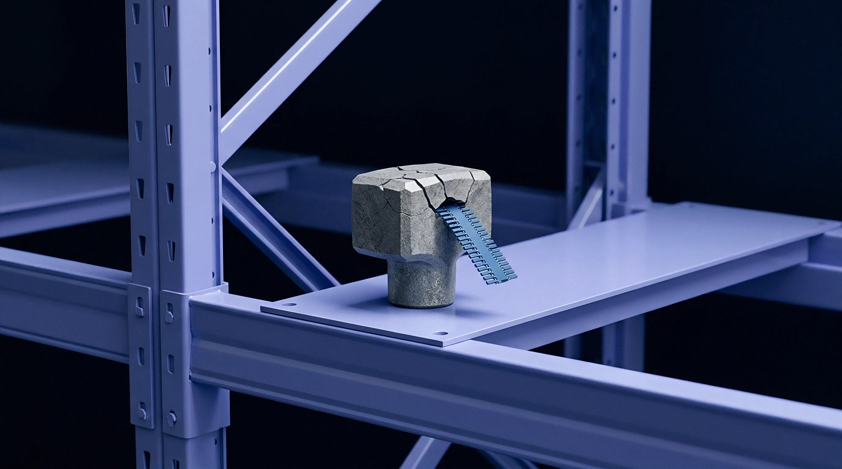
Oxidation
Atmospheric chemical exposure degrades thin metal layers and porous dielectric materials in unsealed micro-coaxial lines. Industrial outdoor deployments, maritime operating environments, and unconditioned electronic housings expose micro-coaxial cables to atmospheric moisture, sulfur gases, salt spray, and corrosive chemical vapors. Chemical oxidation transforms high-conductivity outer surface metals into high-resistivity chemical compounds, fundamentally altering high-frequency RF conduction profiles.
Silver-plated copper center conductors and outer shield strands rely on thin silver surface layers to carry high-frequency currents. Ambient atmospheric sulfur compounds, including hydrogen sulfide, react with surface silver to form silver sulfide tarnishing layers. Silver sulfide exhibits semiconductor-like electrical properties with electrical conductivity orders of magnitude lower than metallic silver.
As silver sulfide thickness grows beyond skin depth dimensions, high-frequency current shifts into lower-conductivity chemical layers, driving insertion loss upward across microwave and millimeter-wave bands.
Moisture ingress into micro-coaxial structures alters both metallic and dielectric loss mechanisms simultaneously. Micro-braid shields draw moisture into internal cable voids through capillary action when outer jackets experience micro-fractures, mechanical abrasion, or unsealed end terminations. Absorbed liquid water possesses a relative dielectric permittivity near 80 and an exceptionally high dielectric loss tangent across microwave frequencies, converting low-loss insulation spaces into high-attenuation signal absorption sites.

Galvanic Corrosion in Micro-Braid Intersections
Micro-braid outer shields bring dissimilar metals into physical contact at strand crossover points and connector crimp barrels. In the presence of condensed atmospheric moisture and ionic contaminants, microscopic galvanic cells form at metallic interfaces.
Galvanic potential differences between tin-plated, silver-plated, and bare copper wire strands drive localized anodic oxidation. Corrosive reactions consume outer metal plating layers, producing non-conductive metallic oxides and hydroxides at strand crossover points. Oxide accumulation insulates intersecting braid strands from one another, disrupting inter-strand cross-conduction current paths.
Disrupted braid conduction forces shield currents to follow long individual wire strand helices rather than uniform tubular outer shell paths. Helical path constraints elevate shield inductance and increase effective outer conductor path lengths, driving high-frequency insertion loss upward while severely degrading cable shielding effectiveness against external interference.

Moisture Absorption and Dielectric Loss Tangent Degradation
Polymeric cable insulation materials display varying degrees of moisture absorption when subjected to humid operating conditions. Solid fluorinated ethylene propylene exhibits low water absorption below 0.01 percent by weight, maintaining stable dielectric loss properties in humid environments.
Microporous expanded polytetrafluoroethylene dielectrics incorporate high internal void volumes to lower effective dielectric constants toward 1.4. Unsealed microporous structures absorb water vapor rapidly under high relative humidity conditions through capillary condensation inside sub-micron pores. Trapped liquid water inside the dielectric core increases effective dielectric constants while raising the composite loss tangent by orders of magnitude.
Elevated loss tangents transform low-loss assemblies into high-loss transmission links within days of unsealed humid exposure.
Hermetic sealing of micro-coaxial connector terminations prevents ambient air exchange into internal dielectric matrices. Application of fluoropolymer potting compounds, dual-wall heat-shrink tubing, or IP67/IP68 sealed bulkhead connectors protects porous dielectrics from moisture contamination during outdoor operations.

Silver Plating Tarnishing and Skin Layer Conduction Losses
Silver electroplating over copper center conductors provides a low-loss conduction path for high-frequency RF signals. Atmospheric sulfur compounds react readily with exposed silver surfaces, forming black silver sulfide films.
Silver sulfide film growth alters electrical conduction within skin depth boundaries. Because RF current density concentrates in the outer surface shell at gigahertz frequencies, even sub-micron sulfur film layers occupy significant fractions of active conduction layers. High resistivity within sulfur films increases total surface resistance, driving linear attenuation upward over operational exposure lifetimes.
Unordered failure modes observed during long-term environmental aging include:
- Silver Sulfide Tarnishing reduces high-frequency surface conductivity along inner conductor skin layers.
- Galvanic Oxide Formation insulates overlapping braid wire crossovers, increasing shield transfer impedance.
- Capillary Moisture Condensation saturates porous dielectric membranes, elevating volumetric dissipation factors.
- Connector Contact Corrosion degrades gold-to-gold contact interfaces, introducing erratic contact resistance points.
- Outer Jacket Environmental Cracking permits direct atmospheric contaminant ingress into internal braid matrices.
Applying tin-lead or pure tin plating over outer braid strands provides higher galvanic corrosion resistance than silver plating in harsh salt-spray environments, sacrificing initial high-frequency insertion loss performance to achieve long-term attenuation stability in corrosive operational fields.
Protecting ultra-fine RF transmission lines against aggressive atmospheric oxidation requires sealing all exposed cable ends before environmental exposure.


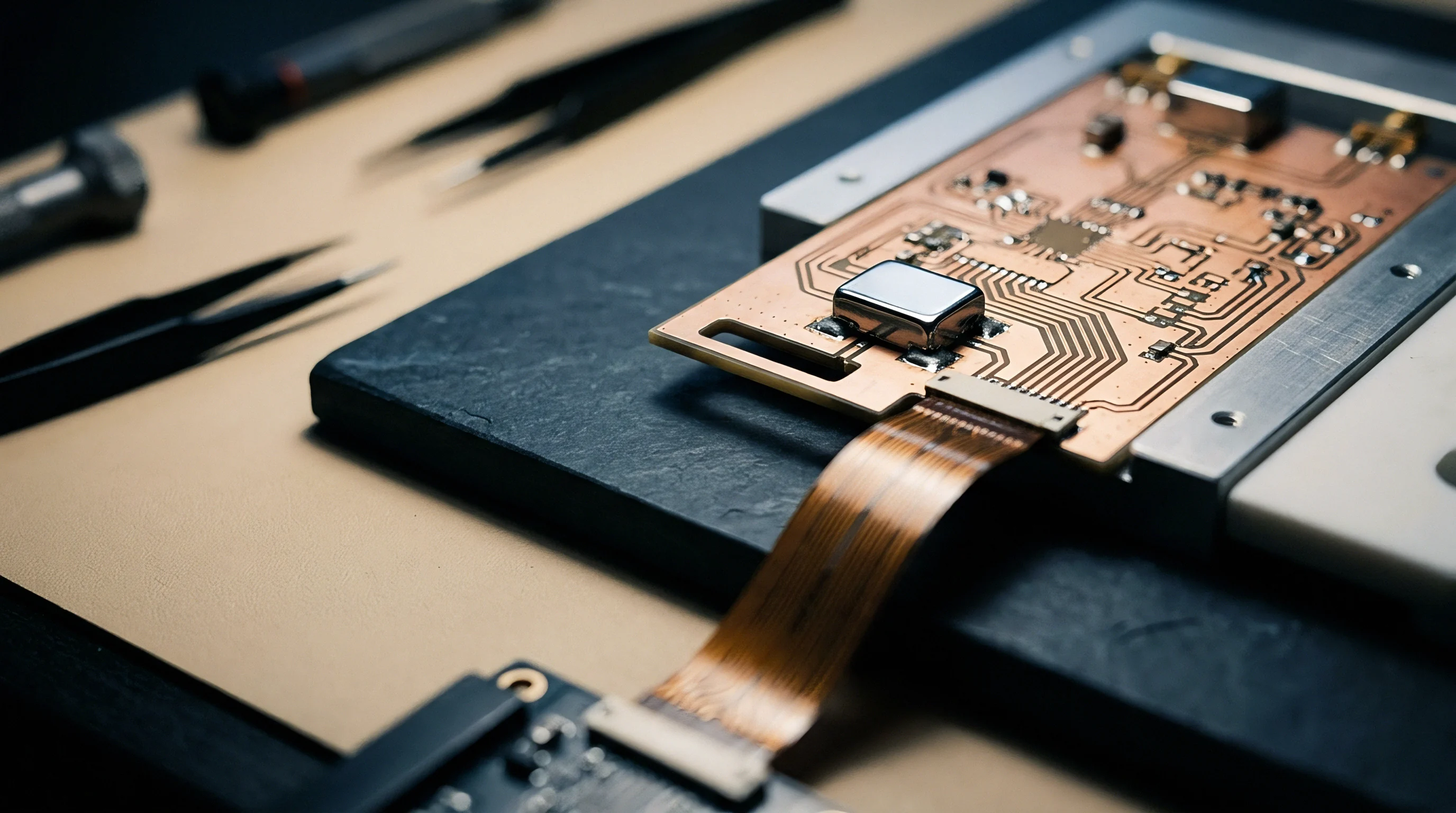
Provision
Designing robust radio frequency systems requires allocating insertion loss budgets across all interconnect components between transceiver chipsets and antenna terminals. Over-allocating RF loss to micro-coaxial cable assemblies degrades total system link margin, forcing transmitters to operate at higher power output levels and shortening battery operating life in mobile IoT devices. Under-allocating loss leads to non-compliant receiver sensitivity figures during final product qualification testing.
Link budget calculations incorporate nominal cable insertion loss figures alongside manufacturing tolerances, thermal drift allowances, flexure degradation margins, and environmental aging factors. Relying solely on room-temperature nominal datasheet attenuation figures guarantees system failure in demanding operational environments. Comprehensive link budget modeling assigns explicit dB loss allowances for every operational degradation mechanism expected over product operating lifespans.
Selecting optimum micro-coaxial cable dimensions involves trade-offs between physical routing constraints, dynamic flex fatigue life, operational frequency bands, and total landed module cost. Choosing larger cable outer diameters reduces baseline attenuation per meter but increases bend radius limits and component costs. Selecting ultra-fine cables simplifies routing in dense enclosures but consumes precious link margin through high conductor losses.

System Link Budget Loss Allocation Modeling
Formulating accurate system link budgets requires breaking total interconnect loss down into constituent baseline and environmental loss variables. Total budgeted RF interconnect attenuation equals nominal baseline cable loss plus thermal drift margins, mechanical flexure margins, connector interface losses, and environmental degradation reserves.
Baseline cable loss scales with cable length and operational carrier frequency. Thermal drift allowances add between 10 percent and 15 percent extra loss for operations reaching upper temperature boundaries around 85 degrees Celsius. Dynamic flexure applications reserve an additional 0.5 dB to 1.5 dB attenuation allowance to accommodate mechanical braid strain and localized impedance disruptions over mechanical service lifespans.
Connector pair loss allocations account for initial insertion loss plus contact degradation across specified mating cycles. Standard micro-coaxial connector pairs contribute approximately 0.2 dB to 0.4 dB loss per mated interface at 5.8 GHz when new, rising toward 0.8 dB after 30 mechanical mating cycles under field servicing conditions.

Frequency-Dependent Cable Radius Selection Metrics
Radio frequency protocol selection fixes operational carrier wavelengths and dictates cable diameter selection logic. Lower carrier frequencies, including sub-GHz LoRaWAN, Sigfox, and NB-IoT bands (868 MHz to 915 MHz), experience modest attenuation across fine micro-coaxial cables, permitting 0.81 mm outer diameter assemblies in space-constrained layouts.
Intermediate carrier bands, including 2.4 GHz Bluetooth Low Energy, Wi-Fi 6, and Zigbee protocols, tolerate cable runs up to 150 mm using 1.13 mm micro-coaxial lines without exceeding 0.3 dB interconnect loss limits. Higher carrier frequencies, including 5.8 GHz Wi-Fi 6E/7 bands and 24 GHz to 39 GHz 5G millimeter-wave links, demand larger 1.37 mm or 1.80 mm microporous ePTFE assemblies to hold interconnect losses within acceptable link budget boundaries.
| Wireless Protocol Standard | Carrier Frequency Band (GHz) | Target Cable Diameter (mm) | Nominal Loss per 100mm Cable (dB) | Thermal and Age Reserve Allocation (dB) | Total Budgeted Interconnect Loss (dB) |
|---|---|---|---|---|---|
| Sub-GHz LoRa / NB-IoT | 0.868 – 0.915 | 0.81 | 0.11 | 0.04 | 0.15 |
| BLE / Zigbee / Wi-Fi 2.4G | 2.400 – 2.483 | 1.13 | 0.16 | 0.06 | 0.22 |
| Wi-Fi 6E / Wi-Fi 7 | 5.150 – 7.125 | 1.37 | 0.23 | 0.09 | 0.32 |
| Satellite NTN / C-Band 5G | 3.400 – 4.200 | 1.32 | 0.18 | 0.07 | 0.25 |
| 5G mmWave FR2 | 24.250 – 39.000 | 1.80 (ePTFE) | 0.42 | 0.18 | 0.60 |
Engineers evaluate protocol bandwidth, receiver noise figures, and available transmitter power levels against cable attenuation metrics to identify maximum allowable interconnect lengths before link performance drops below protocol sensitivity thresholds.

Landed Module Cost against RF Loss Tradeoffs
Sourcing decisions balance component procurement costs against system power budget consequences. Ultra-fine 0.81 mm micro-coaxial assemblies carry low unit purchase prices, often costing $0.25 to $0.40 in production volumes. Larger 1.80 mm microporous ePTFE low-loss cable assemblies cost significantly more, reaching $1.20 to $2.50 per unit due to complex dielectric processing and specialized connector crimping procedures.
Choosing cheaper, higher-loss micro-coaxial assemblies forces system designers to increase active radio power output to overcome interconnect attenuation. Increasing transmitter output power by 1.5 dB to offset cable loss can consume an additional 30 mA to 60 mA of active current from battery supplies during transmit bursts. For battery-powered IoT endpoints transmitting frequent telemetry packets, extra active current draw reduces battery operational lifespan significantly, increasing total cost of ownership through frequent field battery replacements.
Spending $0.45 extra on a low-loss microporous cable assembly reduces transmitter power draw sufficiently to extend sensor battery lifespan from 3.2 years to 5.0 years in field operations. System integrators evaluate component landed costs against operational battery performance metrics when finalizing RF micro-coaxial cable specifications for mass production sourcing.