In-Line Optical Calibration Fixture Design and Repeatability
Rigid kinematic isolation, deterministic clamping vectors, and stable optical projection are mandatory to prevent fixture-induced calibration drift on the line.


Anchor
In production line calibration of optical transceivers, depth engines, and camera modules, a mechanical datum shift of just half a micron under clamping force corrupts the output. High-volume optical assembly requires spatial positioning, target alignment, and sensor orientation to remain rigid through tens of thousands of insertion cycles. The in-line calibration fixture sets the coordinate reference for each unit tested; if the fixture plate flexes under pneumatic pressure, the calibration routine bakes incorrect correction vectors into non-volatile device memory.
A reference design proves out beam shaping or sensor performance on an open optical bench, but taking that setup into volume manufacturing requires repeatable kinematic datums. The host PCB simply isn’t rigid enough ~ raw FR4 thickness varies by over ten percent across a panel, and uneven solder mask creates unstable resting angles. Kinematic mounting isolates the device from board flex by referencing machined points on the optical chassis instead of the PCB laminate.
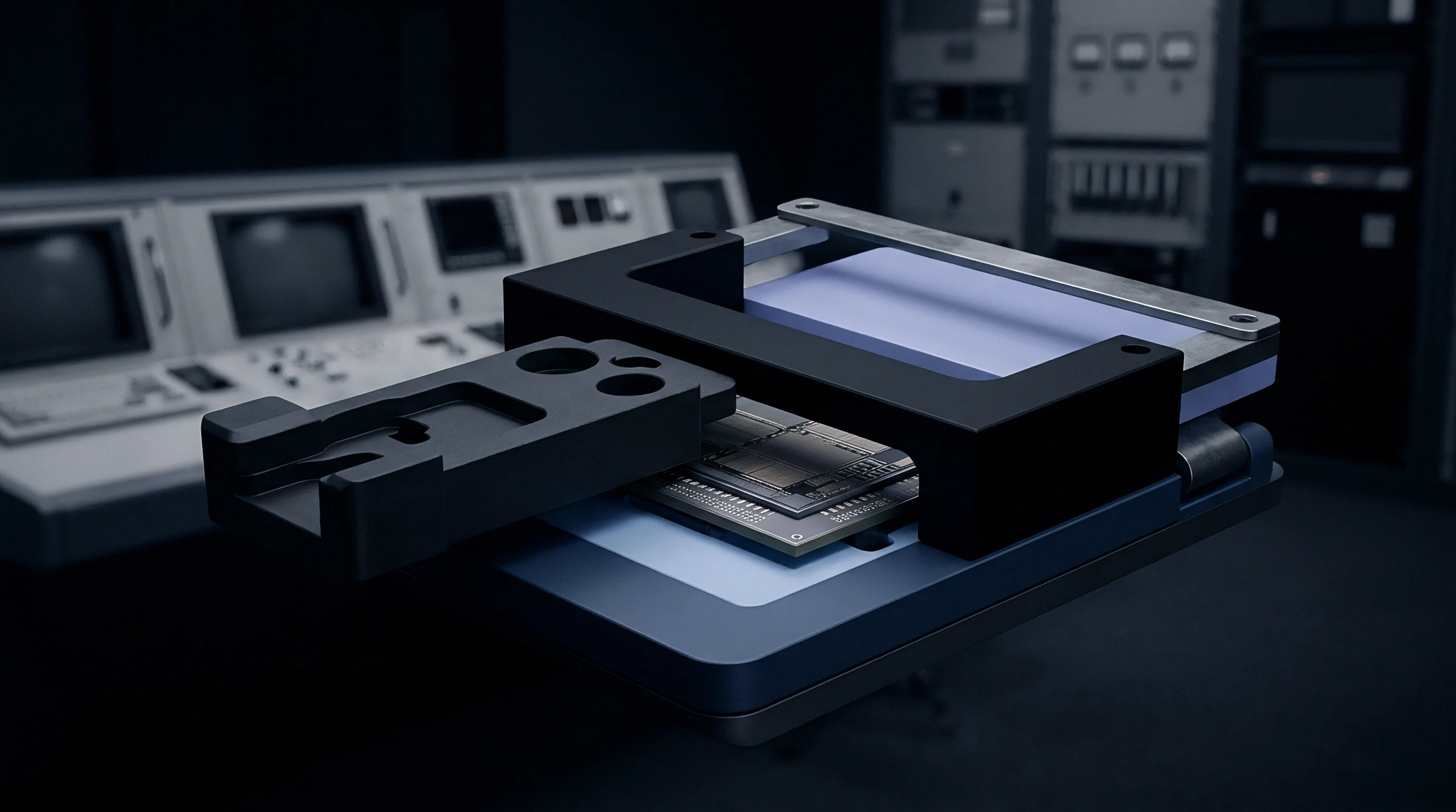
A 3-2-1 kinematic nest resting on hardened silicon nitride balls isolates the optical chassis from board flexure and maintains positioning within two microns across thermal excursions.
Repeatability depends on keeping clamping loads away from alignment surfaces. Pressing directly on glass optics or molded resin lenses causes stress birefringence and distorts lens curvature. Instead, clamping mechanisms apply spring-loaded or pneumatic force directly opposite machined locating pads on the chassis.
FEA modeling verifies that clamping forces sink straight into fixture support pillars without bending the optical axis. For fixtures rated past 100,000 actuations, hardened carbide wear plates or ceramic inserts at each locating datum stop localized wear from drifting the baseline z-height.


Kinematics
Holding an optical module during automated calibration requires controlling all six degrees of freedom without over-constraining the assembly. A traditional Kelvin coupling positions the part deterministically by seating three spherical contacts into a trihedral cup, a vee-groove, and a flat pad, locking all translational and rotational axes at distinct point contacts. When high line speeds make manual placement impractical, the Maxwell configuration offers a sturdier alternative using three radial vee-grooves set at 120 degrees that engage three mating spheres on the carrier.

Mechanical Datum Strategy
Every interface across the fixture chassis works off a strict tolerance budget. Shops grind mounting nests from tool steels such as A2 or D2 heat-treated to 58-62 Rockwell C, or turn to low-expansion alloys like Invar 36 if test chambers cycle in temperature during extended burn-in runs. As an operator or SCARA robot drops a module into place, guide pins align the housing just before the kinematic mount makes final contact.
Using standard cylindrical dowels for sub-micron alignment is a frequent design error ~ even a fraction of a degree in misaligned insertion causes binding. Pairing a diamond pin with a round pin prevents rotational wedging while holding lateral position. Pre-load springs then push the carrier lightly against the primary reference pads before high-pressure pneumatic clamps lock down, protecting precision registration faces from impact damage.
| Interface Topology | Constrained Degrees | Repeatability (µm) | Angular Error (µrad) | Wear Mechanism |
|---|---|---|---|---|
| Kelvin Nest (Cup, Vee, Flat) | 6 (Deterministic) | 0.5 to 1.2 | 5 to 15 | Hertzian contact fretting |
| Maxwell Coupling (3 V-Grooves) | 6 (Deterministic) | 0.8 to 1.8 | 8 to 20 | Groove facet galling |
| Diamond and Round Pin Pair | 4 (X, Y, Pitch, Yaw) | 3.0 to 8.0 | 40 to 120 | Pin shank scoring |
| Planar Vacuum Chuck with Hard Stops | 3 (Z, Pitch, Roll) | 1.5 to 3.5 | 20 to 50 | Debris entrapment |
Force Vector Isolation
Clamping loads cannot be allowed to path through optical elements or distort walls holding lens groups. Standard pneumatic cylinders vary in clamping force as factory air pressure fluctuates; running regulated air through proportional valves holds clamp force stable to within two percent across a shift. Toggle clamps offer mechanical over-center locking so loss of air pressure won’t release the part, though manual toggles introduce operator variation.
Automated cells use air-bearing or flexure-guided stages to position calibration targets relative to the module. Monolithic flexures carved from aluminum or beryllium copper eliminate stick-slip friction, delivering sub-micron stepping across several millimeters of travel. With zero backlash and no lubricants to outgas onto nearby optics, flexures avoid the contamination risks of traditional slides.
Alignment drift frequently traces back to factory air line pressure dropping below operational thresholds during peak shift changes.


Optics
Target projectors inside an in-line fixture use collimators to simulate long throw distances in tight spaces. Calibrating a wide-angle camera module focused at infinity would otherwise take over ten meters of physical path length. Fitting that into a test cell occupying just one square meter of floor space requires multi-element collimator optics or folded mirror paths.
Placing a physical reticle at the collimator’s focal plane projects parallel ray bundles, presenting virtual targets at infinity or designated distances.
Target Projection and Illumination Stability
Integrating spheres produce uniform Lambertian illumination across the field of view, keeping spatial variation under two percent across the fixture aperture. Constant-current drivers supply power to narrowband LEDs or halogen sources feeding the sphere, while photodiode feedback loops adjust for junction thermal shifts and LED aging. Without active feedback, chromaticity and output luminance drift within hours, throwing off white-balance and sensitivity calibration.
Chrome reticle patterns on quartz substrates provide high-contrast target features for MTF, distortion, and axis-centering tests. Quartz has a low expansion coefficient of 0.55 × 10⁻⁶ / K, keeping feature geometry stable under bright illumination. Standard soda-lime glass, at 8.5 × 10⁻⁶ / K, expands enough as internal lamps heat the fixture during twenty-four-hour production runs to introduce target position errors.

Collimator Configuration Metrics
Selecting an in-line optical projector requires balancing focal length, field angle, and exit pupil diameter. The table below outlines parameters across four standard projection architectures.
| Collimator Architecture | Effective Focal Length (mm) | Clear Aperture (mm) | Field Angle (deg) | Wavefront Error (RMS) |
|---|---|---|---|---|
| Off-Axis Parabolic Mirror | 250 to 500 | 50 to 100 | ±2.5 | < λ / 10 at 632.8 nm |
| Achromatic Doublet Array | 100 to 200 | 30 to 50 | ±6.0 | < λ / 4 at 550 nm |
| Multi-Element Telecentric Lens | 50 to 120 | 40 to 80 | ±28.0 | < λ / 6 across VIS |
| Diffractive Pattern Generator | N/A (Fiber Fed) | 10 to 25 | ±45.0 | Pattern specific |
Suppressing stray light inside the test enclosure requires careful material coating. Standard anodized aluminum reflects strongly in the near-infrared, interfering with 850 nm and 940 nm time-of-flight and LiDAR testing. Internal surfaces need inorganic black coatings or structural flocking so internal reflections don’t skew sensor noise floor readings.
Reflective collimators avoid chromatic aberration altogether across visible and IR bands. Off-axis parabolic mirrors let a single test port evaluate multi-spectral sensors without refocusing between visible and infrared channels. However, mounting off-axis parabolas demands tight angular alignment; a tilt error of fifty microradians introduces astigmatism that looks identical to defocus on the device under test.
ISO 10110 drawings govern optical target quality, and omitting surface imperfection thresholds allows vendor micro-scratches to register as false dead-pixel clusters during automated optical sensor bring-up.
Collimator glass should be mounted using potted elastomeric rings or flexure clips. Screwing threaded retaining rings directly against glass stresses the optics, distorting the wavefront and introducing localized astigmatism. Rigid mounts also transfer plant floor vibration ~ from nearby stamping presses or board conveyors ~ directly to the lens, blurring images across multi-frame exposures.


Variance
Evaluating fixture repeatability requires separating measurement errors from actual unit-to-unit production variation. Gage R&R studies isolate system variance against tolerance limits; if Gage R&R consumes more than ten percent of the total tolerance band, the fixture takes up too much error budget, triggering false rejects or letting out-of-spec parts pass.
Uncertainty Budgets
An optical calibration fixture is a multi-stage measurement system whose total uncertainty budget combines individual error sources in quadrature. Mechanical positioning errors, target illumination drift, thermal expansion, optical wavefront degradation, and image quantization noise all add to the overall measurement variance.
Take an active alignment station calibrating a stereoscopic depth sensor where optical axis parallelism is held to 0.05 degrees (3.0 arcminutes). Maintaining test uncertainty below ten percent leaves a total error budget of 0.3 arcminutes (18 arcseconds). Thermal drift in structural components, motion stage wobble, and reticle positioning errors must all fit within that limit.
Sources of Fixture-Induced Error
Fixture variation typically comes down to four mechanisms on the production floor:
- Thermal gradient expansion shifts the baseline distance between target collimators and reference nests over an eight-hour shift. Aluminum tooling plates expand at roughly 23 microns per meter per degree Celsius, pushing target coordinates out of tolerance if cell temperature drifts by more than two degrees.
- Contact datum galling wears down reference faces over thousands of cycles. Microscopic metal transfer alters how the module seats, driving progressive pitch and yaw drift in calibration logs.
- Pneumatic regulator hysteresis causes clamping force to fluctuate. Variable down-force compresses elastomeric gaskets unevenly, shifting sensor tilt relative to the test optic.
- Particulate contamination settles on locating points and collimator optics. A single five-micron dust particle trapped under a locating stop can tilt a small-format camera module by over two milliradians.
General cleanroom air handling helps reduce dust, but in-line fixtures usually need local laminar flow hoods or positive-pressure ionized air knives blowing over the nest during transfers. Control software should track total actuation cycles and lock out the station if verification runs on golden reference units show drift beyond set limits.


Governance
The fixture design transfer package forms the baseline agreement between module buyer and contract manufacturer. Moving a fixture design from an R&D lab to volume production without complete tolerances or documented firmware leads directly to yield drops. The handover package must define every mechanical interface, wiring diagram, control script, and master calibration certificate.

Design Transfer Package Requirements
Documentation needs to be explicit so local plant staff don’t have to guess. The bill of materials must list specific part numbers for kinematic components, pneumatic regulators, positioning stages, and reticles ~ substitutions picked by local buyers often lack the dynamic stiffness or thermal stability assumed in the original design.
- Mechanical CAD archives supplied in native formats along with STEP models, fully annotated with geometric dimensioning and tolerancing for critical datum planes.
- Full electrical schematics detailing sensor wiring, optocoupled I/O, emergency-stop loops, and power distribution buses.
- Optical component certificates verifying collimator focal length, reticle chrome density, surface flatness interferograms, and integrating sphere spectral data traceable to national metrology standards.
- Control software source code including measurement libraries, camera driver dependencies, calibration scripts, and database schema definitions.
- Golden unit verification protocols defining standard check routines with stable, serialized artifact modules to confirm fixture baseline performance before each shift.
The golden unit check sets operating limits: if an artifact shows MTF or spatial positioning beyond three standard deviations from its baseline, the station halts immediately. This keeps a chipped pin or drifting optic from silently corrupting production lots.

Engineering Scope and Ownership Boundaries
Contracts between the OEM and contract manufacturer must state who covers fixture maintenance, recalibration, and design changes. Ownership clauses specify whether custom nests and collimators belong to the buyer or remain factory IP. Explicit rules keep technicians from tweaking fixture code or hard stops to artificially inflate yields during high-volume ramp.
A tooling transfer agreement without explicit source-code escrow leaves the buyer stranded on the production line when the contract manufacturer refuses to release the proprietary calibration engine libraries.
Vague engineering scope turns technical problems into commercial arguments. When yields fall due to fixture drift, factories often point to overly tight optical tolerances while design teams blame poor nest maintenance or temperature swings. Setting explicit Gage R&R limits in the supply agreement avoids these arguments before production starts.

Economics
In-line calibration takes up a large share of assembly cycle time and equipment budget. A sixty-second calibration cycle limits throughput to sixty units per hour per station. Hitting an annual target of one million units on a two-shift schedule requires running ten parallel cells, each representing significant fabrication and NRE investment.

Capital Expenditure and Non-Recurring Engineering
Precision calibration fixtures require custom frames, scientific illumination, and diffraction-limited optics. High-resolution linear stages with sub-micron encoders drive costs up further. A complete cell with dual collimators, a six-axis stage, and integrated spectral monitoring generally runs between $80,000 and $180,000 to build and qualify.
Developing the fixture architecture requires 400 to 800 hours of optical, mechanical, and software design. At design house rates of $175 to $250 per hour, NRE easily tops $120,000 before the first unit reaches the plant floor. Skimping on NRE by dropping flexure stages or using off-the-shelf lenses usually backfires into ongoing scrap costs and constant downtime for manual recalibration.

Cycle Time Breakdown and Throughput Optimization
Trimming even a second from the calibration cycle reduces the number of parallel stations needed on the floor. The table below breaks down cycle time for a dual-camera active alignment routine.
| Process Operation | Duration (s) | Limiting Mechanism | Optimization Strategy |
|---|---|---|---|
| Part Loading and Kinematic Clamping | 3.5 | Pneumatic cylinder travel time | High-speed voice coil actuators |
| Sensor Initialization and Handshake | 2.0 | I2C/I3C bus communication rate | Higher clock speeds, DMA transfers |
| Active Optical Alignment Stepping | 8.5 | Hexapod mechanical settling time | Closed-loop piezo stages with feedforward |
| Multi-Field Image Acquisition | 4.0 | Sensor frame rate and exposure time | Strobed high-intensity illumination |
| Data Processing and Matrix Calculation | 3.0 | Host processor core performance | GPU acceleration, parallelized pipelines |
| EEPROM / OTP Memory Burning | 2.5 | Non-volatile memory write endurance | Page-write optimization algorithms |
| Unclamping and Ejection | 1.5 | Safety clamp release interlocks | Optimized pneumatic exhaust paths |
The total routine takes 25.0 seconds, giving a theoretical maximum of 144 units per hour per station at 100 percent utilization. At a realistic 85 percent Overall Equipment Effectiveness (OEE), actual output drops to about 122 units per hour. Overlapping tasks ~ like running matrix calculations while a second nest loads the next module ~ improves overall capital efficiency.
Finalizing calibration algorithms before volume production prevents expensive hardware changes later. Modifying target geometry after sign-off means re-machining fixture plates, manufacturing new reticles, and recalibrating collimators. Line downtime while waiting for retrofits costs thousands of dollars a day, quickly wiping out any savings from rushing optical modeling upfront.


Qualification
Transitioning a tool from prototype testing to volume manufacturing depends on formal qualification. Fixtures that work flawlessly in a quiet lab often behave differently on a production floor subject to floor vibration, electrical noise from conveyors, and varying operator technique.

Shift Drift Monitoring and Golden Artifact Tracking
Capability metrics track fixture stability over time. Standard quality protocols look for a Cpk of at least 1.33 on non-critical features and 1.67 on critical optical alignments. Calculating valid Cpk metrics requires continuous logging of parameters like focal length, axis offset, and sensor tilt across shifts.
Golden units provide the physical baseline. These serialized modules are measured on lab coordinate measuring machines and interferometers before going into service. Standard procedures require technicians to run them through fixtures at fixed intervals:
- Shift start verification catches mechanical alignment errors from cleaning, bumps, or thermal changes before operators start running production parts.
- Post-maintenance audit runs verify that replacing cylinders, pins, or illumination lamps restores baseline performance without introducing systemic offset.
- Batch changeover confirmation ensures modified nesting inserts sit flush against structural plates without trapped debris.
- Unscheduled line stop clearance checks whether electrical surges or mechanical jams bent pins or shifted optics during an emergency stop.

What Shifts Golden Unit Alignments over Time?
Even reference artifacts drift if handled poorly. Body heat from an operator touching the metal housing can cause temporary dimensional changes of several microns. Artifacts should stay in protective cases inside the test cell so they match ambient room temperature.
Periodic lab recertification confirms the artifact itself hasn’t drifted due to a dropped housing or worn alignment hole.
Internal components inevitably wear over time. Linear bearings, seals, and kinematic contact points all degrade under high cycle counts. Tracking actuations to trigger preventive maintenance ensures worn parts are swapped during planned downtime rather than after a failure corrupts a batch of production units.
Contract manufacturers carry financial liability for scrapped production lots if line logs show fixtures ran out of spec without technician intervention.