Wideband Transceiver Antenna Detuning Effects on Power Amplifier Efficiency Metrics
Antenna detuning alters PA load impedance, degrading efficiency and thermal headroom across wideband transceivers during high-VSWR operational shifts.


Load

Environmental Impedance Shifting at the RF Interface
A wideband transceiver paired with an electrically small antenna works across a complex impedance plane that shifts constantly in real-world use. Frequency ranges spanning sub-GHz bands from 863 MHz to 928 MHz or cellular bands from 698 MHz to 2200 MHz impose hard bandwidth limits on passive matching circuits. The moment an antenna leaves a controlled 50-ohm test bench, its surroundings alter its input impedance.
Hands, nearby metal chassis, liquid containers, and plastic housings all disturb the reactive near-field environment. That dielectric loading introduces parasitic capacitance and changes the radiating structure’s effective electrical length, pulling resonance away from the targeted channel.
That resonance shift immediately produces an impedance mismatch at the antenna port. Across typical deployments, the real part of antenna impedance can collapse from 50 ohms down below 10 ohms or spike past 200 ohms, paired with heavy inductive or capacitive reactance. As reflected voltage waves grow relative to forward waves, the Voltage Standing Wave Ratio often climbs from a clean 1.1:1 up to 6:1 or worse.
That mismatch redefines the load impedance seen by the output stage of the integrated or discrete radio frequency Power Amplifier.
Transceiver designs depend on an optimal load line to efficiently convert DC power into RF radiation. To deliver peak output power alongside top power-added efficiency, the output transistor needs a very specific fundamental load impedance. Once antenna detuning rotates and shifts the load away from that sweet spot, the dynamic load line strays from its proper operating window between knee voltage and breakdown.
The output stage drops out of efficient power transfer and into a hot, inefficient operating regime.

Wideband Operational Bandwidth Constraints
Keeping a low Voltage Standing Wave Ratio across a wide band means working against the physical limits of passive structures. Tight antenna dimensions in asset trackers, smart meters, and handheld radios suppress radiation resistance and store high reactive energy in the near field. Antennas with a high quality factor are especially sensitive to detuning ~ even a slight shift in surrounding permittivity can trigger severe reflection back into the transceiver.
Broadband matching networks smooth out frequency-dependent variation to a degree, but they cannot fix physical near-field loading changes that occur in the field. Discrete matching networks made of surface-mount inductors and capacitors also add insertion loss that builds up across broad spans. When the antenna detunes, the matching network’s transformation combined with external reactive shifts routinely pushes the PA transistor into high-loss zones on the Smith chart.
A transceiver has to hit required output levels across regional channels without overheating or draining the battery too quickly. A board layout operating in European sub-GHz channels around 868 MHz sees noticeably different dielectric loading when deployed in North American 915 MHz bands. Managing this requires tracking how these shifting load conditions travel directly back to the transistor drain node.

Mechanical Enclosure and Proximity Interfaces
Housing an antenna inside a plastic enclosure adds a fixed dielectric load that RF design must account for upfront. Materials like polycarbonate, ABS, and nylon carry relative permittivity values from 2.2 to 3.8, pulling the antenna’s natural resonance down. On top of that, tolerances in wall thickness, potting compound volume, and battery placement create unit-to-unit baseline variations.
In actual use, proximity shifts cause far wider impedance swings. A mobile tracking unit detunes differently if someone holds it, attaches it to a steel frame, or leaves it in open air. Human tissue acts as a lossy dielectric with high relative permittivity, pulling resonance down while swallowing part of the radiated signal.
The efficiency loss hits twice over: energy dissipates directly into tissue, while another portion bounces back toward the transceiver’s power amplifier because of the abrupt impedance shift.
Industrial settings bring similar issues near steel structures. Placing an antenna within a fraction of a wavelength of metal suppresses radiation resistance and drives heavy reactive currents into the ground plane. In compact and mobile wireless designs, maintaining a steady 50-ohm load in the real world is essentially impossible.

Key Variables Governing Antenna Impedance Instability
The extent of the impedance shift at the RF port comes down to a few key physical factors that can be evaluated during board design:
- Antenna Quality Factor sets the ratio of stored to radiated energy per cycle, directly controlling bandwidth and sensitivity to nearby objects.
- Near-Field Boundary Distance defines the spatial volume around the radiator where objects create the strongest reactive loading.
- Substrate Relative Permittivity controls the electrical length of PCB trace antennas, setting the baseline frequency shift caused by housing materials.
- Ground Plane Geometry shapes return current paths, dictating how close metal alters radiation resistance and input impedance.
- Operating Frequency Span sets the bandwidth range across which the passive matching network must handle complex loads.
Module datasheets often promise rated output power and efficiency across an operating band. But those figures assume a clean 50-ohm load measured on a bench test fixture, leaving out the real-world impedance shifts caused by enclosures and changing environments.


Reflection

S-Parameters and Reflection Coefficient Mechanics
Tracking antenna detuning requires measuring the complex reflection coefficient at the power amplifier boundary. The S11 parameter gives the ratio of reflected to incident voltage waves at the transceiver output. Calculated from the complex load and nominal system impedances, this coefficient determines how power splits between radiated energy, heat, and internal reflection.
As an antenna detunes, the reflection coefficient magnitude rises toward unity. A return loss of 20 dB (VSWR of 1.22:1) means just one percent of power reflects back. If detuning drops return loss down to 3 dB (VSWR of 5.85:1), fully fifty percent of the power from the final amplifier stage bounces straight back into the output network.
The phase angle of this reflection sweeps around the Smith chart as the electrical distance between transistor and antenna changes with frequency.
That phase angle dictates the specific stress placed on the PA transistor. Depending on how the reflected wave aligns with the internal voltage waveform, peak drain voltage can double or drain current can spike past safe limits. Amplifier behavior shifts dramatically along an equal-VSWR circle as the phase angle rotates through 360 degrees.
Dynamic Drain Load Line Distortion
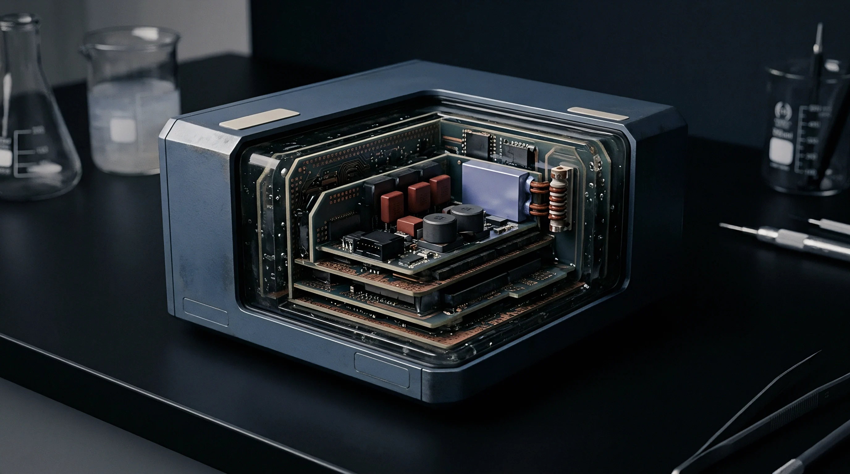
The PA output stage modulates current through its semiconductor channel via a gate or base signal. To achieve strong power transfer and high efficiency, the load line needs to cross right where maximum linear drain current meets minimum knee voltage. Complex reflections distort this straight load line into an ellipse on the current-voltage plane.
An elliptical path forces the transistor to handle high current and high drain-to-source voltage at the same time. That overlap boosts internal power dissipation during the RF cycle, dragging down efficiency. If an inductive load shift expands the voltage peak above the DC supply rail, sub-micron CMOS processes risk gate-oxide breakdown or hot-carrier degradation.
If the shift is capacitive, the dynamic load line drops into the knee region early while current is still high. The transistor saturates prematurely, clipping the waveform and driving up harmonic distortion. Filtering those harmonics to meet regulatory limits adds insertion loss to the output network and further hits overall efficiency.
Conducted output power drops by 3.2 dB when a 4:1 VSWR mismatch with a worst-case inductive phase angle is presented to the transceiver RF terminal.

Standing Wave Voltage Peaks and Current Nodes
Forward and reflected waves combining on the microstrip trace create standing waves. Voltage and current settle into stationary peaks and nodes spaced at quarter-wavelength intervals along the line. Where these peaks land relative to the amplifier output depends entirely on the reflection phase angle.
When a voltage peak settles at the PA output, dielectric stress rises across surface-mount capacitors and inductors in the RF path. Ratings that are fine under a matched load get exceeded under high VSWR, leading to component breakdown or early failure. Conversely, high current nodes increase series resistive losses in PCB traces and inductor windings, turning forward power into heat before it ever gets radiated.
Standing waves also throw off directional couplers and power detectors used for automatic level control. Detectors calibrated for forward voltage give faulty readings when strong standing waves are present. Control firmware can respond by boosting output power when it shouldn’t, putting even more thermal stress on the power amplifier.

Mismatch Loss Quantifications across VSWR Values
Linking VSWR, return loss, and reflection loss mathematically helps separate radiation drops from internal amplifier losses. The power lost purely to reflection is mismatch loss, derived directly from the reflection coefficient magnitude:
Mismatch Loss = -10 log10(1 – |S11|^2)
Working into a 2:1 VSWR introduces a 0.51 dB mismatch loss, reflecting roughly 11 percent of power. At 4:1 VSWR, mismatch loss grows to 1.94 dB ~ a 36 percent reflection. If severe detuning pushes VSWR to 10:1, mismatch loss climbs to 4.81 dB, sending 67 percent of forward power back into transceiver components.
These reflection numbers only cover power rejected at the antenna port. They leave out the additional power turned into heat inside the silicon junction from load line distortion. Overall transceiver degradation combines raw reflection loss with this internal efficiency drop.
Running a transceiver into a severe mismatch without load line protection drives up junction temperatures, shortening component lifespans and triggering thermal throttling in the RF front end.


Dissipation
Drain Efficiency versus Power Added Efficiency Metrics
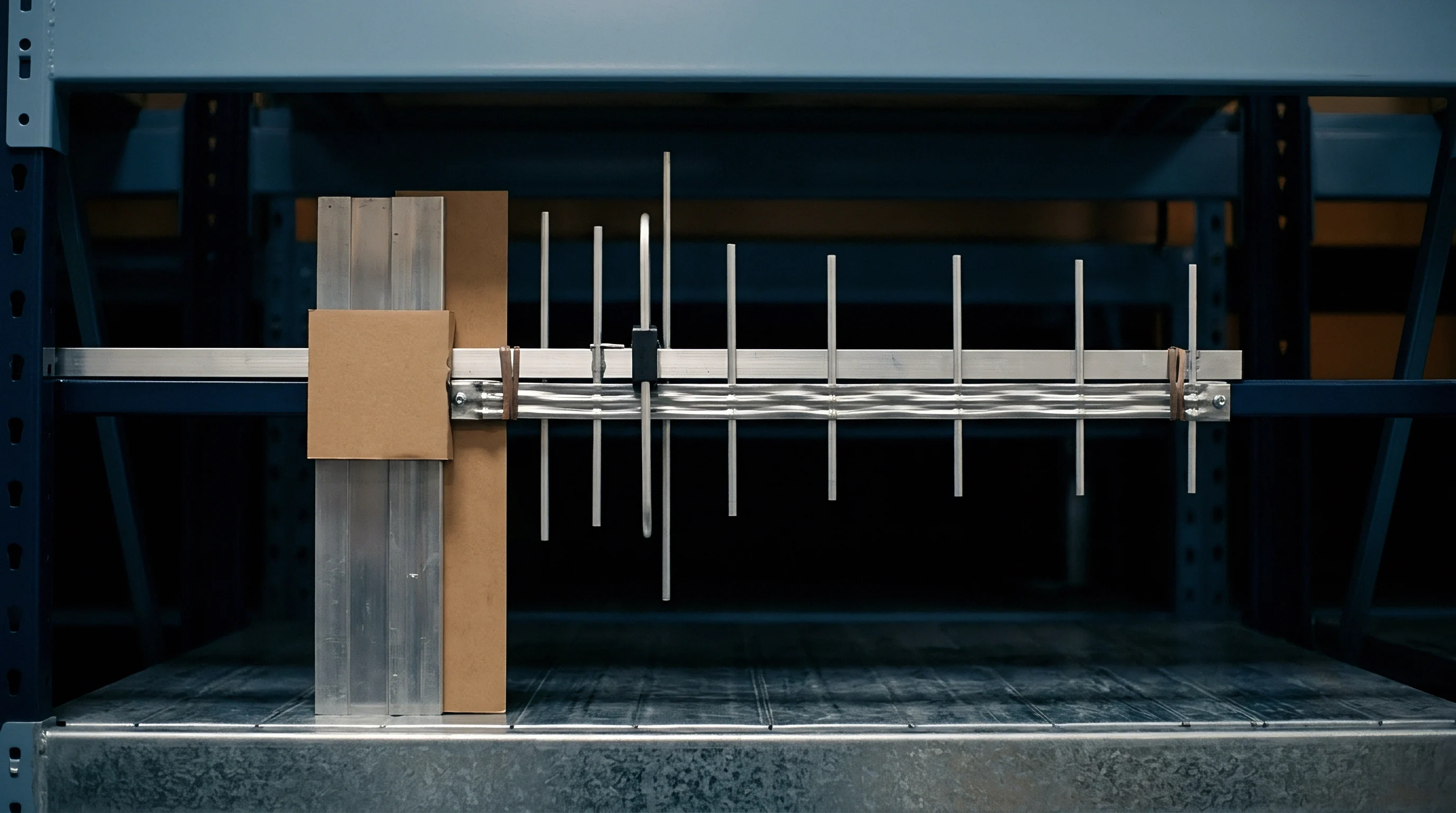
Engineers rely on two main metrics to track efficiency loss under detuning: Drain Efficiency and Power Added Efficiency. Drain Efficiency gives the ratio of RF output power to DC power consumed by the output transistor stage:
Drain Efficiency = P_out / P_DC
Drain Efficiency captures the output stage’s conversion ability, but ignores drive power from preceding stages. Power Added Efficiency factors in that input power to give a full picture:
PAE = (P_out – P_in) / P_DC
Into a clean 50-ohm load, a modern sub-GHz or cellular PA reaches 45 to 65 percent Drain Efficiency in class AB or class F setups, with PAE running between 40 and 60 percent. When detuning alters the load, both numbers collapse.
As load impedance strays from Zopt, RF output drops while DC current stays flat or rises. Whatever DC power isn’t radiated gets dumped as heat into the amplifier silicon. Lower PAE directly translates to faster battery drain and higher thermal loads inside the transceiver package.

How Does Complex Load Impedance Degrade Drain Efficiency?
Drain Efficiency drops under complex loads because of phase shifts between drain voltage and current. In a well-tuned switching or linear PA, current flows mainly when voltage across the device is at its lowest, keeping instantaneous voltage-current products small and internal dissipation low.
Reactive loads offset voltage and current waveforms. An inductive load makes voltage lag current, keeping the transistor at high voltage while channel current is still falling. A capacitive load makes voltage lead current, bringing current up while voltage across the drain remains high.
That overlapping drives heavy power loss twice per RF cycle. The amplifier acts less like a high-efficiency switch and more like a resistor, dumping heat straight into the substrate. Thermal dissipation rises even if overall DC current stays steady or drops, simply because conversion efficiency drops off a cliff.
Phase shifts also corrupt harmonic impedance terminations needed for high-efficiency operation in Class E, F, or inverse F topologies. These designs rely on accurate second and third harmonic terminations to square up voltage and current waveforms. Detuning ruins that harmonic shaping, pulling Drain Efficiency down toward un-tuned Class A levels.
A high quality factor antenna detuned by enclosure proximity converts over seventy percent of supplied DC energy directly into internal package heat.

Thermal Overhead and Silicon Junction Stress
Heat dissipated inside the PA transistor raises its junction temperature, dictated by dissipated power, ambient conditions, and thermal resistance from channel to ground plane:
T_junction = T_ambient + (P_dissipated Theta_JA)
Here Theta_JA is the junction-to-ambient thermal resistance in °C/W. In compact IoT boards or handheld devices, small PCB areas and lack of heatsinks severely limit heat dissipation.
If detuning bumps internal dissipation from 200 mW to 800 mW in a QFN package with a Theta_JA of 50 °C/W, junction temperature rise jumps from 10 °C to 40 °C above ambient. In an industrial setup at 60 °C ambient, that puts the junction at 100 °C ~ uncomfortably close to silicon reliability limits.
High junction temperatures cause secondary problems. Silicon carrier mobility drops as heat builds, lowering transconductance and maximum drive current. As PA gain drops, preceding stages have to drive harder to maintain target output levels, pulling even more total system current.

Measured Transceiver Efficiency across Load Mismatch States
Bench measurements under varying VSWR conditions illustrate how detuning plays out in practice. Testing an 868 MHz sub-GHz transceiver rated for +20 dBm output into a variable load-pull setup produces the results shown below.
| VSWR Ratio | Phase Angle (deg) | Conducted Power (dBm) | Drain Current (mA) | Drain Efficiency (%) | PAE (%) | Thermal Rise (°C) |
|---|---|---|---|---|---|---|
| 1.0:1 | 0 | 20.1 | 110 | 58.2 | 53.1 | 4.2 |
| 2.0:1 | 45 | 19.3 | 118 | 45.1 | 40.2 | 7.8 |
| 2.0:1 | 225 | 18.8 | 105 | 41.3 | 36.5 | 8.5 |
| 4.0:1 | 90 | 17.8 | 135 | 28.3 | 23.8 | 18.1 |
| 4.0:1 | 270 | 16.9 | 98 | 27.1 | 22.4 | 16.4 |
| 6.0:1 | 135 | 15.2 | 152 | 17.8 | 13.9 | 26.9 |
| 6.0:1 | 315 | 14.1 | 92 | 16.1 | 12.2 | 22.1 |
| Data measured at V_DD = 3.3V, RF input power = +3 dBm, fundamental frequency = 868.00 MHz, ambient room temperature = 25 °C. Thermal rise calculated relative to PCB ground plane. | ||||||
The data shows how much impedance phase angle affects drain current and heat, even at a fixed VSWR. At 4.0:1 VSWR, an inductive phase pulls drain current up to 135 mA and drives thermal rise to 18.1 °C while PAE drops to 23.8 percent. A capacitive phase at that same 4.0:1 VSWR cuts drain current to 98 mA due to clipping, but conducted power falls to 16.9 dBm, leaving PAE at a similarly weak 22.4 percent.
Under heavy detuning, high-current phase angles drain batteries rapidly, while low-current phase angles degrade transmit range by dropping output power. Sizing batteries for long service life becomes a much larger challenge when the RF front end faces continuous detuning.
A useful rule of thumb applies here: doubling the standing wave ratio cuts power-added efficiency by roughly a third while doubling junction temperature rise.


Contour

Load-Pull Characterization Techniques
Evaluating PA behavior under load mismatch takes more than standard 50-ohm small-signal S-parameters. Load-pull testing uses automated impedance tuners to present mapped complex loads to the RF port while measuring output power, DC current, PAE, and harmonic levels.
This generates closed contour families across the Smith chart. Constant VSWR circles center on the origin, overlaid with constant power and efficiency contours. In a well-matched PA, peak power and peak efficiency contours land near each other close to the center or along the target load line.
Detuning shifts the load impedance across these contour lines. Moving out from the efficiency peak toward the edge of the chart cuts across tightly spaced efficiency curves. These maps show exactly how sensitive a PA is to phase shifts, highlighting whether performance degrades gradually or falls off a cliff along certain impedance vectors.

Wideband Contour Compression and Phase Sensitivity
For wideband transceivers, load-pull characterization has to be repeated across channels. The optimal load Zopt shifts with frequency as internal parasitics and matching network phase angles change. An antenna mismatch that looks manageable at 868 MHz can easily land in a high-dissipation zone at 915 MHz.
Wideband contour plots often show contour compression, where efficiency lines pack together in certain quadrants. Operating in these compressed regions means minor environmental shifts cause sharp, abrupt drops in PAE and output power, making transceiver behavior hyper-sensitive to nearby objects.
Bench characterization of a sub-GHz transceiver working into a 4:1 VSWR mismatch showed a 32 percent drop in power-added efficiency at 868 MHz. That measurement underscores the gap between 50-ohm datasheet claims and real-world embedded radio performance.

Parametric Oscillations and Mismatch Instability
Severe detuning doesn’t just hurt efficiency ~ it can trigger instability in the power amplifier itself. Extreme load phase angles can flip internal feedback from negative to positive, meeting the Barkhausen stability criterion at unintended frequencies.
This shows up as sub-harmonic oscillations, spurious emissions, or out-of-band spectral growth. Spurious oscillations draw heavy DC power, cutting fundamental Drain Efficiency while spilling interference into adjacent channels. In CMOS transceivers, parametric oscillations can create localized high-current paths that lead directly to electrical overstress failure.
To ensure unconditional stability, Rollett’s stability factor K and the auxiliary measure mu must stay above unity across all operating frequencies and load phases:
K = (1 – |S11|^2 – |S22|^2 + |Delta|^2) / (2 |S12 S21|)
When detuning changes the load seen by the transistor drain, small-signal and large-signal S-parameters shift, dragging K below unity. The circuit becomes conditionally stable, where specific load phases can trigger destructive high-frequency oscillations.

Operational Failure Modes Driven by Antenna Mismatch
Severe mismatch pushes transceivers past performance degradation into actual failure modes that break links and shorten hardware life:
- Spurious Emission Violations happen when distortion generates harmonic or intermodulation products that exceed regulatory band limits under high VSWR.
- Thermal Throttling Lockout occurs when internal sensors trigger automatic power cuts, dropping link budget below receiver sensitivity.
- Battery Voltage Droop Instability happens when current surges into inductive mismatches pull supply rails below reset thresholds, causing unexpected MCU reboots.
- Drain Junction Dielectric Breakdown occurs when transient voltage spikes exceed semiconductor breakdown limits during high-VSWR inductive swings.
Whether closed-loop digital pre-distortion can reliably track fast-moving impedance shifts without generating transient spectral splatter remains an open challenge across hardware platforms.


Compensation

Hardware-Level Detuning Mitigation Networks
Mitigating efficiency loss from detuning requires dedicated hardware in the RF front end. Selecting an approach means balancing circuit complexity, bill of materials cost, board footprint, and baseline insertion loss against the risks of load mismatch.
RF isolators offer strong load decoupling, passing forward power while dumping reflected energy into a 50-ohm termination resistor. Ferrite isolators provide over 20 dB isolation across set bands, but their size, cost, and frequency limits exclude them from small sub-GHz IoT designs. Fixed attenuator pads are a cheap alternative, placing series loss between PA and antenna to dampen reflections.
A 3 dB pad ensures reflected power returning to the PA drops by 6 dB, capping worst-case VSWR seen by the amplifier under 3:1 no matter what happens at the antenna. The trade-off is losing 50 percent of conducted transmit power under all conditions, which rules it out for battery-powered devices.
Quadrature balanced PAs handle mismatch by splitting input power across two identical amplifier stages via a 90-degree hybrid coupler and combining them with a second coupler. Reflected waves arrive at the output coupler out of phase and dump into an isolation load instead of hitting the transistor drains. Balanced PAs maintain flat PAE and steady output across wide phase swings, but require twice the silicon area, draw more DC power at lower outputs, and demand careful phase-matched layout routing.

Dynamic Impedance Matching and Adaptive Tuning
Adaptive tuning adjusts the front-end matching network on the fly as loads shift. Closed-loop aperture and impedance tuning systems use directional couplers, phase/amplitude detectors, and reconfigurable reactive networks to restore matching in real time.
Reconfigurable components rely on barium strontium titanate (BST) varactors, MEMS switches, or high-linearity RF CMOS switch arrays. When the antenna detunes, directional sensors sample forward and reflected voltage so control algorithms can calculate complex load impedance. Digitally switched capacitor banks then adjust capacitance to transform the load back toward 50 ohms before it reaches the PA terminal.
While dynamic tuning restores PAE and lowers junction temperatures, it brings trade-offs. Reconfigurable capacitor arrays add insertion loss under matched conditions, cutting baseline efficiency by 0.5 dB to 1.5 dB. The tuning loop also takes processing time and power to settle, leaving the PA exposed during transient mismatch periods.
| Mitigation Strategy | Baseline Loss (dB) | PCB Area (mm²) | Unit Cost Impact ($) | PAE Retained at 4:1 VSWR (%) | System Complexity |
|---|---|---|---|---|---|
| Uncompensated Front-End | 0.0 | 0.0 | 0.00 | 22 – 28 | Baseline |
| Fixed 3 dB Attenuator Pad | 3.0 | 12.0 | 0.05 | 25 – 30 | Very Low |
| Ferrite RF Isolator | 0.6 | 25.0 | 1.85 | 45 – 50 | Low |
| Quadrature Balanced PA | 0.8 | 40.0 | 1.20 | 42 – 48 | High |
| Closed-Loop Adaptive Tuner | 1.2 | 18.0 | 0.75 | 38 – 44 | Very High |

Regulatory Emission Compliance under Detuning
Detuning directly affects compliance with radio standards like ETSI EN 300 220 in European sub-GHz bands and FCC Part 15 subpart C in North America. These rules set hard legal limits on effective radiated power (ERP), spurious emissions, and adjacent channel leakage ratio (ACLR).
Altered load lines and non-linear distortion increase spurious emissions when an antenna detunes. Second and third harmonic levels can jump by 10 to 20 dB at high-VSWR phase angles. An uncompensated transceiver that easily passes compliance on a 50-ohm bench fixture can quickly fail once placed in a plastic housing or held in a hand.
Compliance testing under ETSI EN 300 220 Clause 4.3.5 mandates that harmonic emissions remain below -36 dBm across all operational loading states, forcing manufacturers to integrate higher-order output filtering despite the associated insertion loss.
Standard qualification requires testing radios under forced mismatch using load-pull fixtures to verify spurious outputs stay compliant across all 360 degrees of reflection phase. Failing harmonic limits under detuned states invalidates certification, putting products at risk of enforcement actions or recalls.
Procurement contracts for high-volume radio modules often include explicit clauses defining performance tolerances into a 3:1 VSWR load across all phase angles, shifting financial liability to suppliers if detuning causes regulatory non-compliance in the field.


Margin

System Link Budget Degradation Calculations
The real-world effect of detuning on wireless links comes down to the system link budget. Link budget math combines transmit power, antenna gains, path loss, and receiver sensitivity to calculate available fade margin:
Fade Margin = P_tx + G_tx – Path_Loss + G_rx – Sensitivity
Detuning degrades this budget in two ways: reduced conducted power from PA efficiency loss, and loss of radiation efficiency from mismatch rejection. Total effective loss subtracts directly from available link margin.
Take a sub-GHz industrial sensor link designed for 1000 meters line-of-sight range at 868 MHz using 100 kbps 2-GFSK modulation. Nominal parameters are +14 dBm transmit power, 0 dBi antenna gain on both ends, and -104 dBm receiver sensitivity. Free-space path loss at 1000 meters is roughly 91.2 dB, giving an intended fade margin of 26.8 dB under clean conditions.
If environmental detuning produces a 5:1 VSWR at the transmit antenna, reflection loss knocks off 2.5 dB. At the same time, load line distortion drops Drain Efficiency, forcing automatic level control or supply voltage collapse to reduce conducted output by another 3.5 dB. The combined 6.0 dB drop reduces fade margin to 20.8 dB.
In non-line-of-sight indoor settings where path loss exponents jump from 2.0 to 3.5, losing 6 dB cuts operational coverage range in half.

Field Range and Power Budget Tradeoffs
Specifying wideband transceivers involves direct trade-offs between link reliability, battery sizing, and unit cost. Selecting a battery based solely on 50-ohm datasheet specifications risks field failures in applications prone to dynamic detuning.
If a product specification targets a ten-year battery life transmitting 100 messages daily, battery sizing must factor in worst-case current draw. Bench tests show that working into a 4:1 VSWR increases average drain current by up to 23 percent to maintain output power, while airtime per message can double if packet loss forces retries due to degraded SNR.
Energy consumed per successful transmission rises quickly under detuned conditions:
Energy_per_message = V_bat I_detuned Airtime (1 + Retry_Rate)
Ignoring detuning in early power calculations results in undersized primary lithium batteries that fail years ahead of schedule, creating heavy field maintenance costs.

Verification Audit Procedures for Front-End Sourcing
To verify a transceiver module meets field reliability needs under load mismatch, engineering teams should execute a thorough qualification sequence before volume sign-off:
- Measure small-signal S11 across the full operating band using a calibrated network analyzer with the module inside its final housing and under expected proximity loading.
- Map output power, DC current, and PAE across a full 360-degree phase circle at VSWR levels of 2:1, 4:1, and 6:1 using an automated load-pull system.
- Check spurious emissions and harmonic containment across all load-pull impedance states to ensure regulatory compliance under worst-case detuning.
- Use high-resolution thermal imaging during continuous transmission into high-VSWR inductive phases to locate silicon hot spots.
- Run field coverage tests with units in real handling conditions, logging packet error rates, RSSI, and battery voltage drop profiles in real time.
Mismatch tolerances are specified directly in module sourcing contracts, defining maximum current surge and minimum conducted power across a 3:1 VSWR circle before committing to volume orders.
Ensuring operational integrity across deployments requires treating the PA, matching network, mechanical enclosure, and antenna as one coupled electro-thermal system. Designing wideband wireless devices with real load-pull data, clear tolerances, and proper front-end compensation preserves link margins, protects battery life, and ensures regulatory compliance in real-world environments.