Meaning
Automated test equipment is a computer controlled instrument system that executes programmed test routines on manufactured circuit boards and radio frequency modules to verify electrical performance against manufacturing tolerances. Production lines deploy automated test equipment to validate solder joint integrity, parametric voltage levels, and signal propagation speeds before units receive their final protective enclosure. Testing stops at the boundary where physical assembly finishes and environmental stress screening begins.
Test Execution
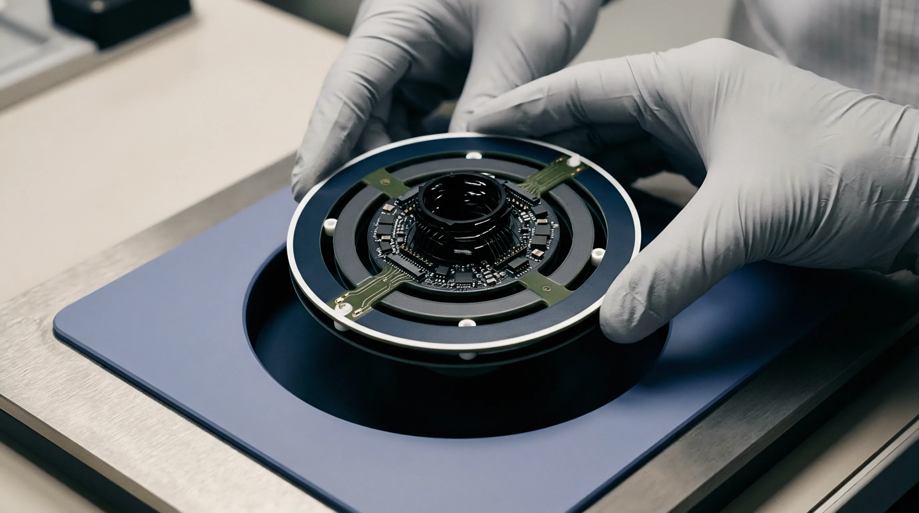
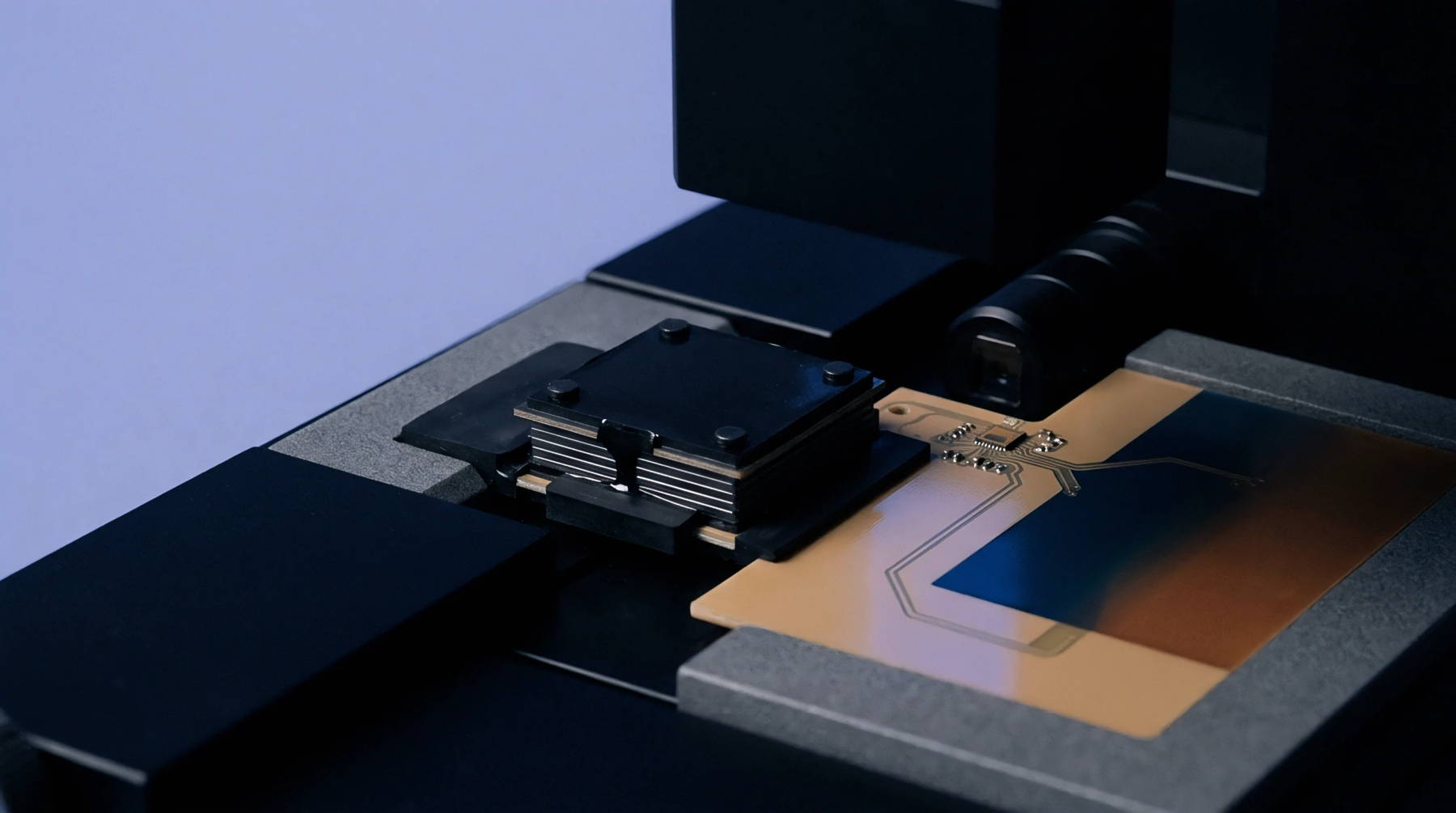
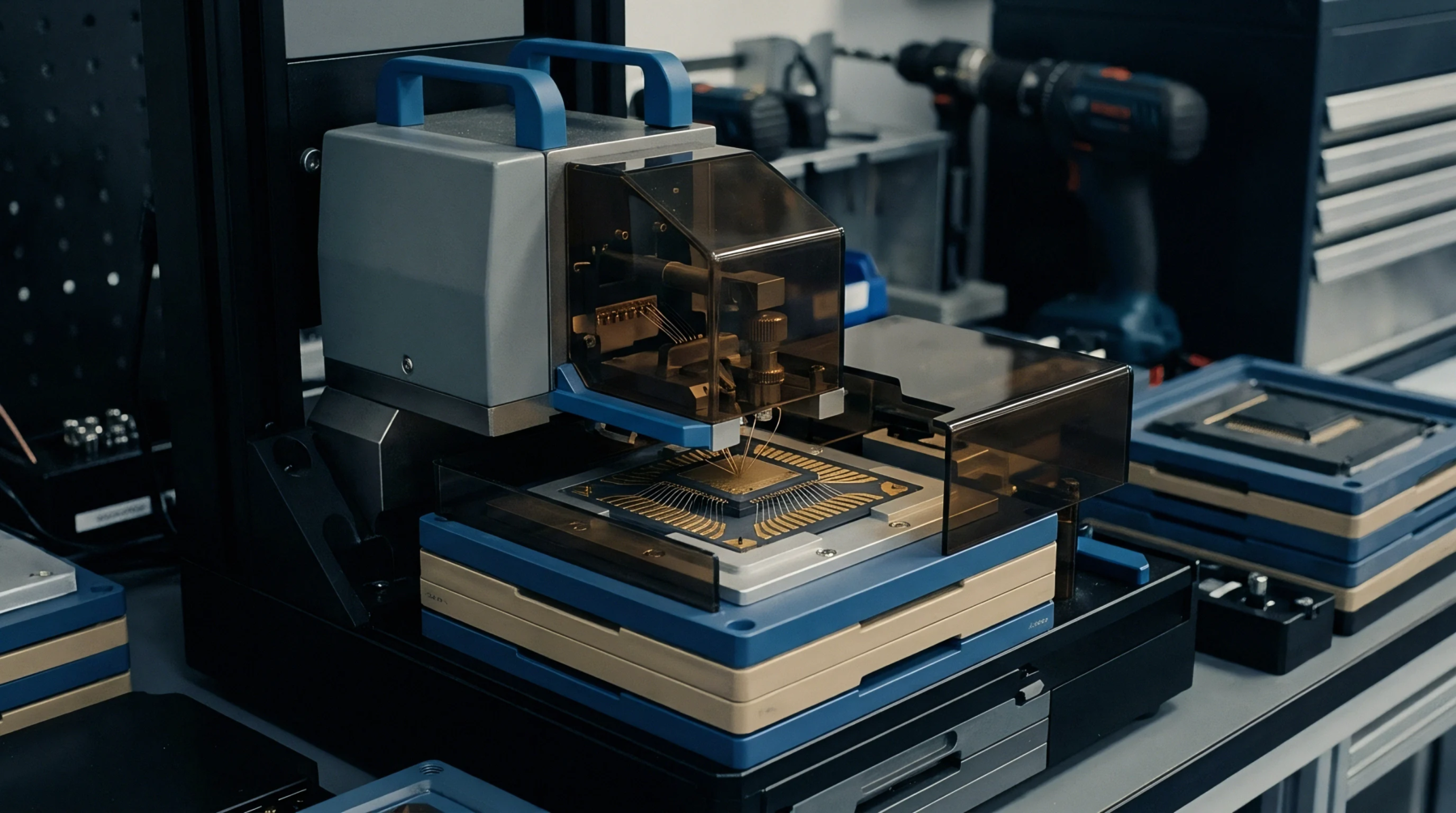
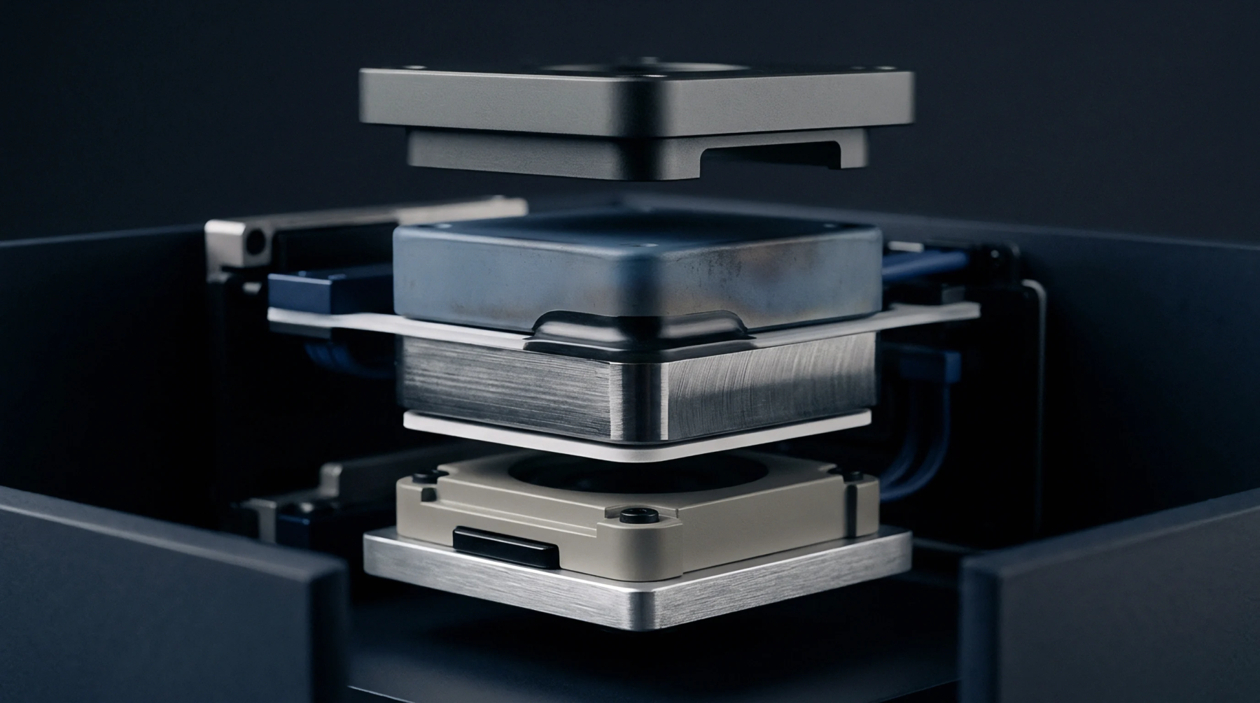
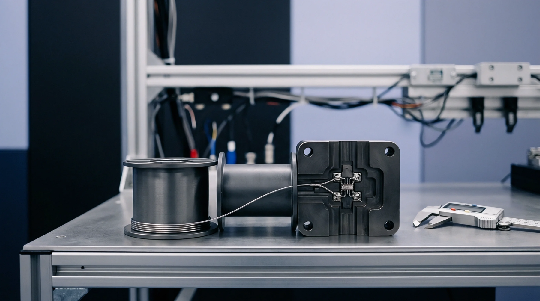
Software scripts drive the mechanical fixture to press spring probes against designated test points while high speed digital pins stimulate the board. Signal generators inject specific radio frequencies into the antenna path while spectrum analyzers measure the resulting harmonic suppression and output power. Hardware switches route measurement channels through multiplexers to minimize cable capacitance errors during high frequency calibration routines.
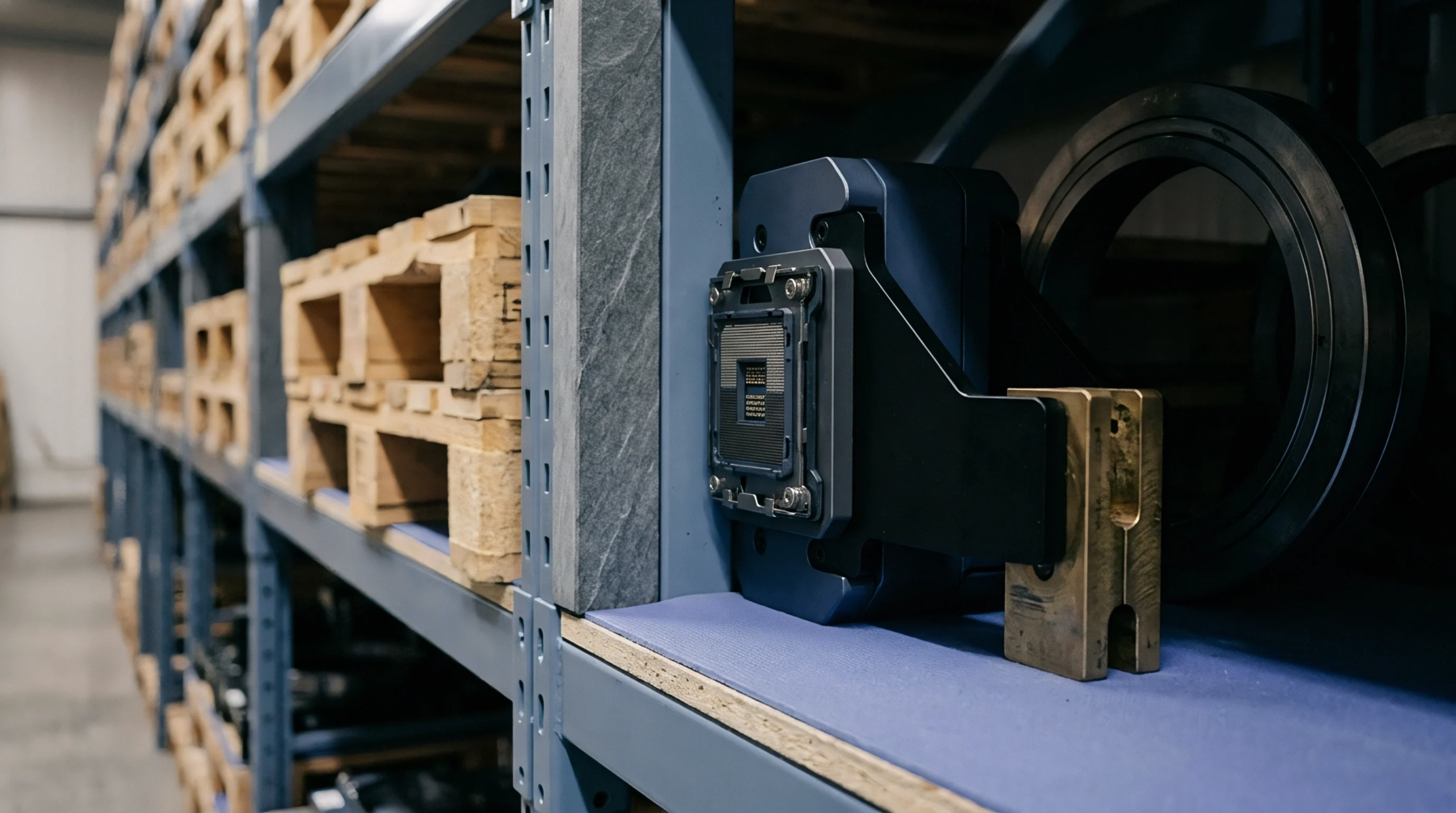
Fixture wear alters contact resistance over thousands of insertions, forcing maintenance teams to clean gold plated pins regularly to prevent false rejection of good assemblies.
System Integration
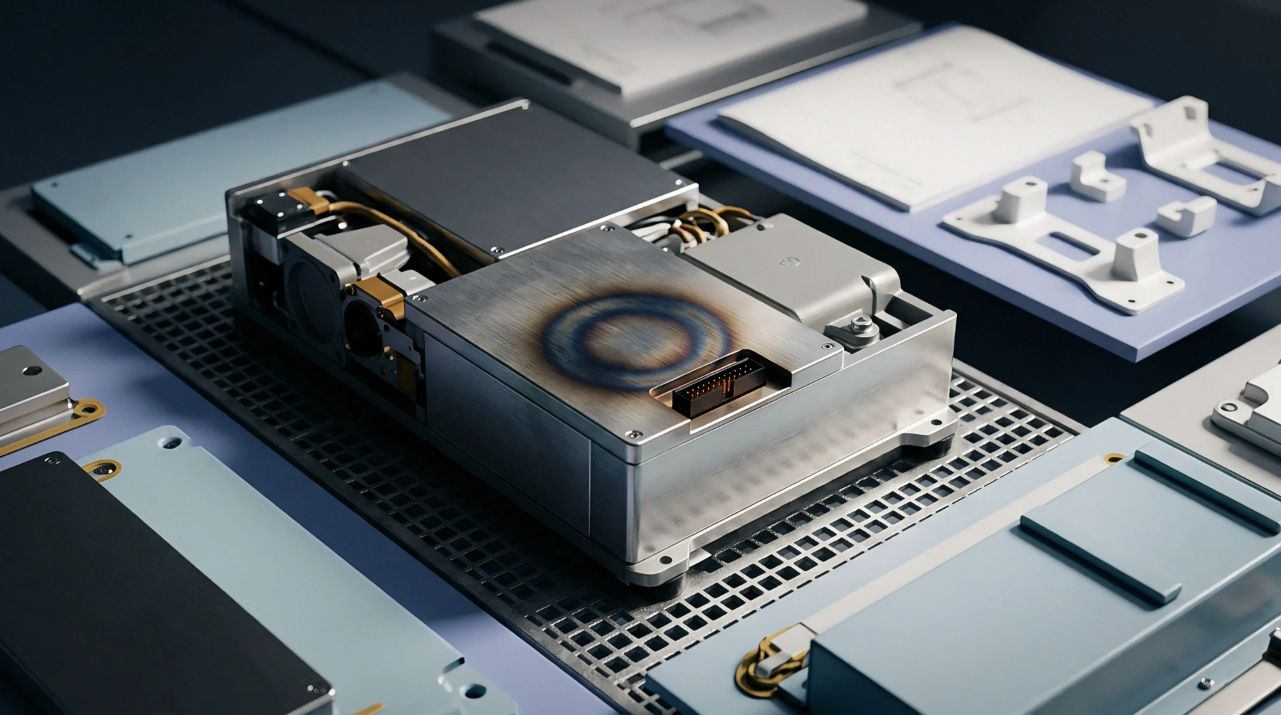
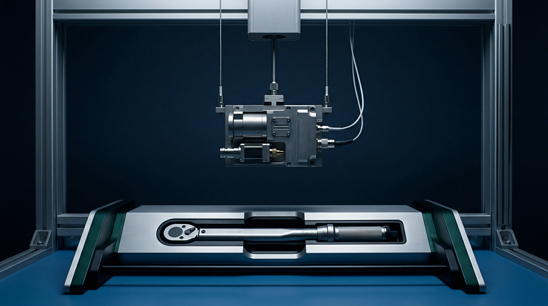
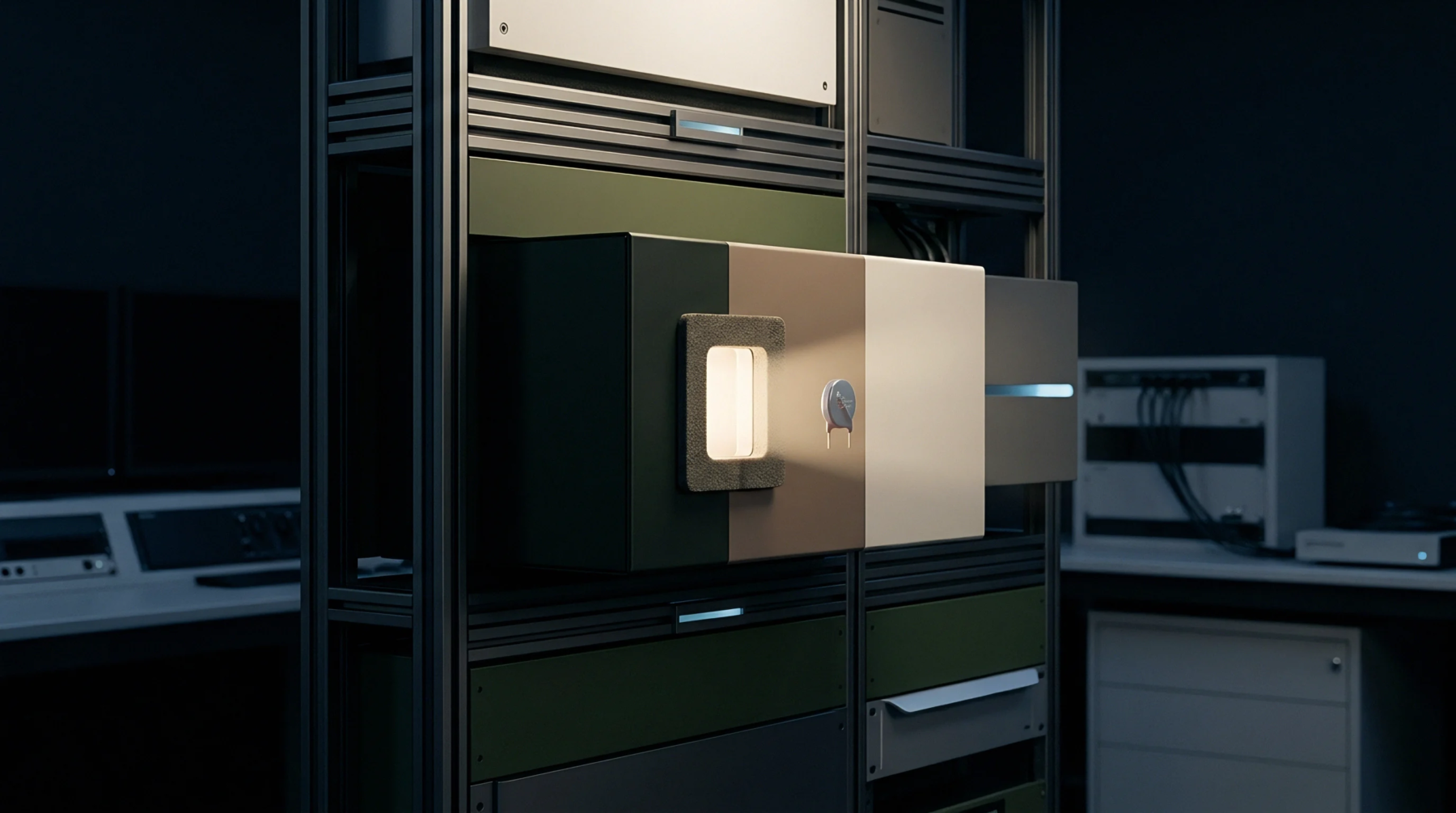
Mechanical housing dimensions dictate how radio frequency cables route past internal power supplies without creating electromagnetic interference that corrupts low level measurements. Power distribution networks must handle sudden current draws during processor boot cycles without dropping supply voltage below the operational threshold required by the device under test. Thermal dissipation inside the sealed cabinet influences calibration stability because prolonged high load testing generates internal heat that shifts reference voltage generators.
Buyers qualify the complete assembly against contractual specifications during the final factory acceptance test before shipping the hardware to the integration floor.
Data Verification
Statistical process control software analyzes pass rates across consecutive shifts to detect subtle parameter drift in component lots supplied by third party vendors. Engineers adjust test limits only when component variance exceeds historical process capability indices established during pilot production runs. Operators sign off on the calibration audit report before starting the daily production shift to ensure measurement traceability remains intact.
Fault logs generate a detailed record that helps manufacturing engineers trace recurring solder bridging issues back to specific stencil printer settings.